

Coupling agent applicator for ultrasonography department
A technology of applicator and coupling, which is applied in ultrasonic/acoustic/infrasonic diagnosis, medical science, acoustic diagnosis, etc. It can solve the problems of couplant waste, couplant not applied, and inability to apply couplant, etc., to achieve effective control, Ease of use
- Summary
- Abstract
- Description
- Claims
- Application Information
AI Technical Summary
Problems solved by technology
Method used
Image

Examples
Embodiment Construction
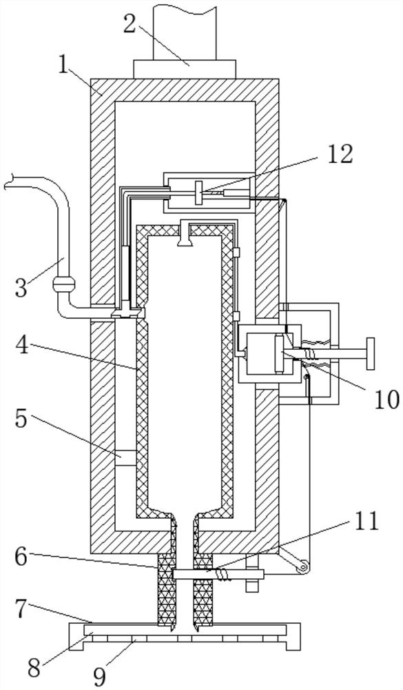
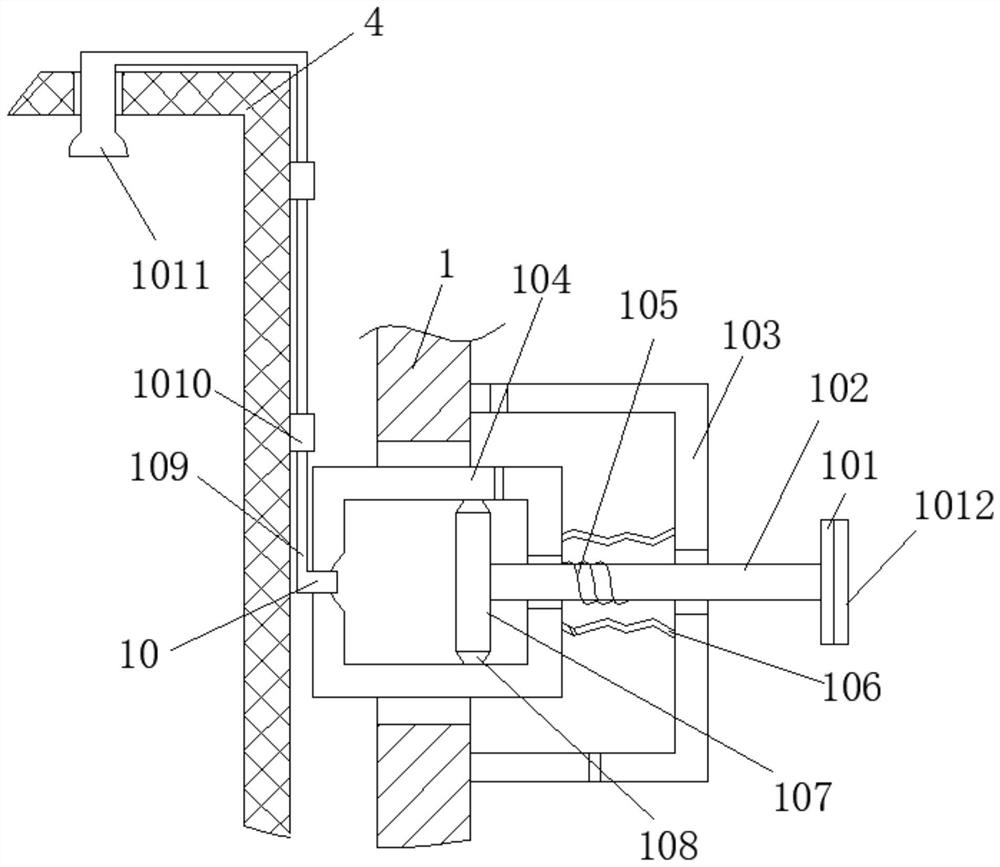
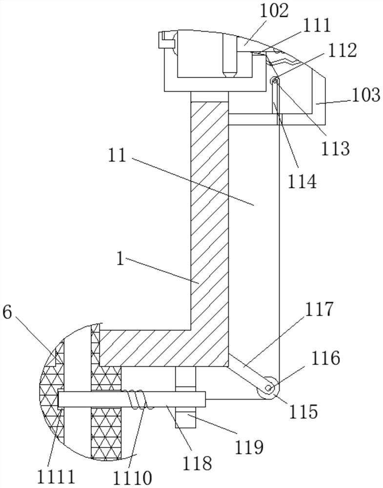
[0026] Attached below Figure 1-5 The present invention is further described with embodiment:
[0027]An ultrasonic coupling agent applicator, comprising a support box 1 and a connecting rod 2, the connecting rod 2 is fixedly arranged on the outer top wall of the support box 1, and the side wall of the support box 1 is fixedly inserted with a liquid inlet pipe 3, and One end of the liquid inlet pipe 3 located in the support box 1 is arranged in the quantitative box 4, the quantitative box 4 is fixedly arranged in the support box 1 by the fixed rod 5, and the bottom plate of the quantitative box 4 is provided with a liquid outlet pipe 6, and the liquid outlet pipe 6 is fixedly inserted on the bottom plate of the support box 1, and the liquid outlet pipe 6 is fixedly inserted on the silica gel support shell 7, and the silica gel support shell 7 is provided with a storage chamber 8, and the storage chamber 8 and the quantitative box 4 pass through the liquid outlet pipe 6 are co...
PUM
 Abstract
Description
Claims
Application Information