
Driving control device of intravascular ultrasonic probe and intravascular ultrasonic imaging system

An ultrasonic probe and blood vessel technology, which is applied in the fields of ultrasonic/sonic/infrasonic equipment control, ultrasonic/sonic/infrasonic Permian technology, ultrasonic/sonic/infrasonic image/data processing, etc., can solve the problem of high cost and assembly Difficulty, poor synchronization effect and other problems, to achieve the effect of easy production and assembly, simplified control strategy, and simplified structure

Pending Publication Date: 2021-02-05
SONOSCAPE MEDICAL CORP
View PDF0 Cites 4 Cited by
  • Summary
  • Abstract
  • Description
  • Claims
  • Application Information

AI Technical Summary

Problems solved by technology

[0005] However, the synchronization effect between the motors is poor, and the slight error between the two will cause the dislocation of the synthesis of the two slices during image synthesis, resulting in the problem of poor synthesis of imaging. If complex control logic and control structure Controlling the synchronization of motors is not only costly, but also difficult to control and relatively difficult to assemble
[0006] To sum up, how to solve the problem of poor composite effect of ring scan imaging and retraction imaging is a technical problem that needs to be solved at present

Method used


Image

  • Driving control device of intravascular ultrasonic probe and intravascular ultrasonic imaging system
  • Driving control device of intravascular ultrasonic probe and intravascular ultrasonic imaging system
  • Driving control device of intravascular ultrasonic probe and intravascular ultrasonic imaging system

Examples


Embodiment Construction

[0055] The following will clearly and completely describe the technical solutions in the embodiments of the present invention with reference to the accompanying drawings in the embodiments of the present invention. Obviously, the described embodiments are only some, not all, embodiments of the present invention. Based on the embodiments of the present invention, all other embodiments obtained by persons of ordinary skill in the art without making creative efforts belong to the protection scope of the present invention.

[0056] The core of the present invention is to provide a drive control device for an intravascular ultrasound probe. The ring scan imaging and retraction imaging of the drive control device use the same input power, which can improve the synchronization of the ring scan imaging and retraction imaging, so that the two The composite effect of the image is good.

[0057] Another core of the present invention is to provide an intravascular ultrasound imaging syste...


PUM


Abstract

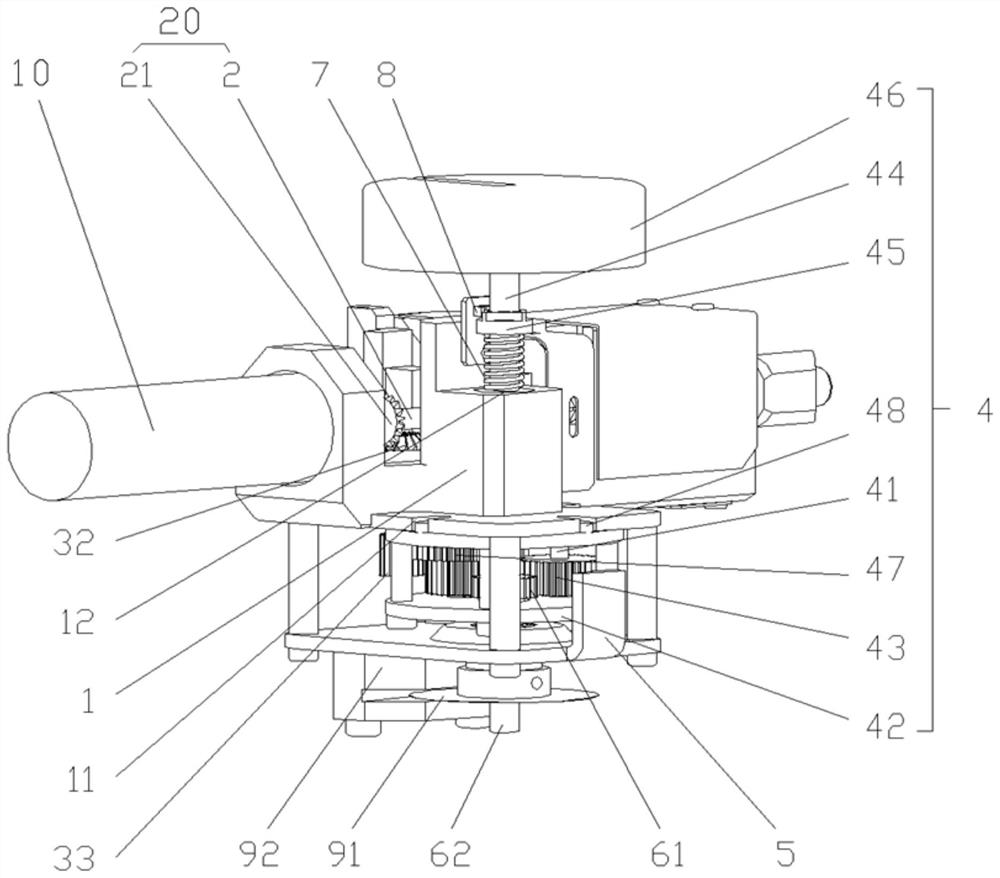
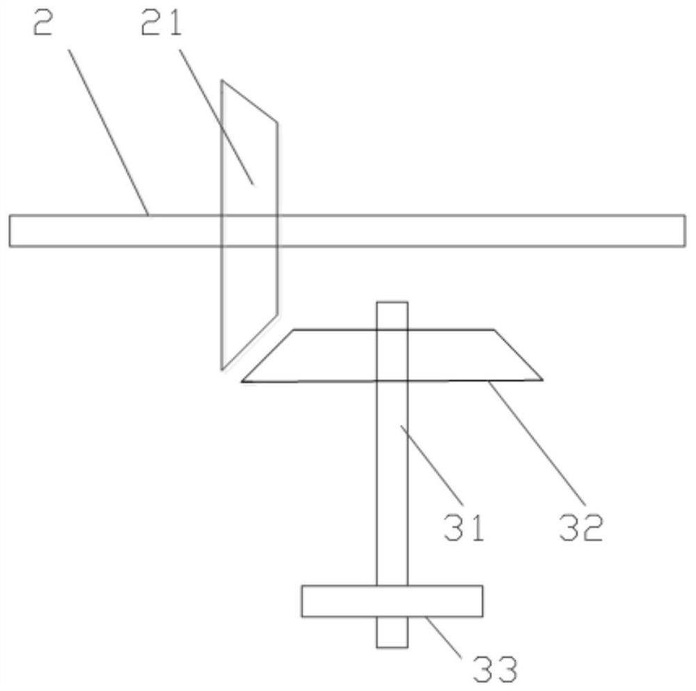
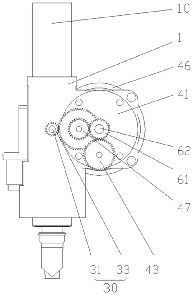
The invention discloses a driving control device of an intravascular ultrasonic probe and an intravascular ultrasonic imaging system. The driving control device of the intravascular ultrasonic probe comprises a driving mechanism, a first transmission mechanism and a second transmission mechanism, wherein the first transmission mechanism drives the probe to do withdrawing motion; the second transmission mechanism drives the probe to do rotating motion; the first transmission mechanism and the second transmission mechanism are respectively in transmission connection with an output portion of thedriving mechanism; and when the driving mechanism works, the first transmission mechanism and the second transmission mechanism can simultaneously output power. The driving control device has the advantages that one driving mechanism is used for driving the two transmission mechanisms, thus, when the driving mechanism outputs the power, the first transmission mechanism and the second transmissionmechanism are in a power output state; the same power source is used, so that good synchronism of the output of the first transmission mechanism and the output of the second transmission mechanism can be ensured; a complicated control strategy of the driving mechanism is not needed; structure simplification and control strategy simplification can be realized; production and assembly are facilitated; and the cost is easy to control.

Description

technical field [0001] The invention relates to the technical field of medical equipment, and more specifically, to a drive control device for an intravascular ultrasonic probe. In addition, the present invention also relates to an intravascular ultrasonic imaging system comprising the above-mentioned drive control device for the intravascular ultrasonic probe. Background technique [0002] Intravascular ultrasound is an imaging technique in which an ultrasound transducer is inserted into the cardiovascular cavity through a catheter to obtain the cross-sectional morphology or blood flow pattern of the cardiovascular system using ultrasound, which can be used to examine the condition of the vessel wall. During the imaging process, the ultrasonic transducer performs rotational movement and retraction movement in the blood vessel to realize image formation. [0003] The existing intravascular ultrasound driver mainly includes a rotating motor, a retracting motor, and a sliding...

Claims


Application Information

Patent Timeline
IPC IPC(8): A61B8/08A61B8/12A61B8/00H02K7/10H02K7/116
CPCA61B8/0891A61B8/12A61B8/4444A61B8/54H02K7/10H02K7/116H02K7/1163
Inventor 李政朱彦聪
Owner SONOSCAPE MEDICAL CORP
Learn More