
Chemical liquid reaction kettle capable of uniformly conveying materials

A reaction kettle and feeding technology, which is applied in the field of chemical liquid reaction kettle, can solve the problems of wasting reactants, affecting the purity, time-consuming and labor-intensive cleaning, etc., and achieve the effect of avoiding bending, avoiding pollution problems, and improving stirring efficiency

Inactive Publication Date: 2021-02-05
张映梅
View PDF0 Cites 0 Cited by
  • Summary
  • Abstract
  • Description
  • Claims
  • Application Information

AI Technical Summary

Problems solved by technology

[0003] The purpose of the present invention is to provide a chemical liquid reaction kettle capable of uniform feeding, to solve the problem of liquid mixed reaction in the reaction kettle, when the reaction material needs to be added in the middle of the reaction, the material is directly put into contact with the liquid mixture, due to the existence of certain The height difference, during feeding, the liquid mixture will splash in the reactor, and the splashing of the material on the inner wall of the reactor not only wastes the reactants, but also takes time and effort to clean the mixture adhered to the inner wall of the reactor. The attachment of the mixture in place to the inner wall of the reactor will affect the purity of the environment in the reactor, resulting in low efficiency of secondary chemical reaction technical problems

Method used


Image

  • Chemical liquid reaction kettle capable of uniformly conveying materials
  • Chemical liquid reaction kettle capable of uniformly conveying materials
  • Chemical liquid reaction kettle capable of uniformly conveying materials

Examples


Embodiment 1

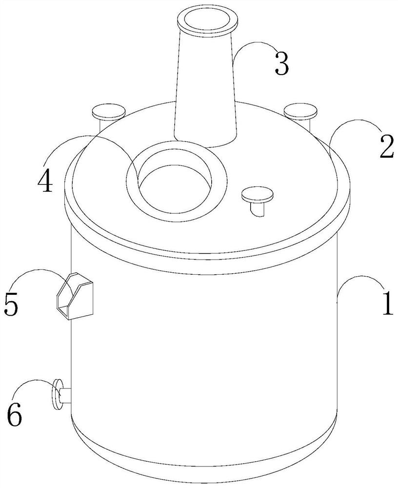
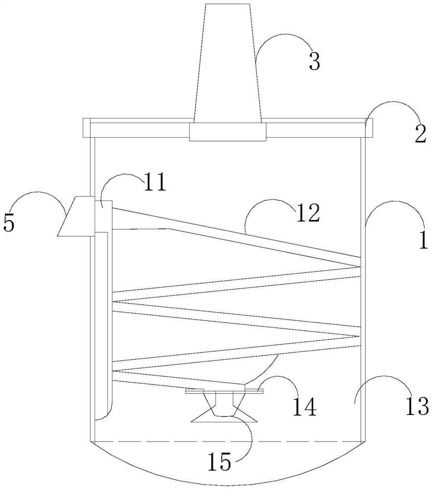
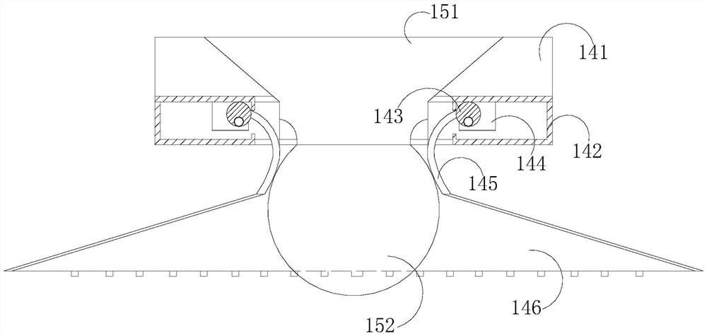
[0027] Such as Figure 1-Figure 6 As shown, the present invention provides a chemical liquid reaction kettle capable of uniform feeding, and its structure includes a kettle body 1, an end cover 2, a frame 3, an observation window 4, a feeding port 5, and a discharge port 6. The kettle body 1 is provided with an end cover 2, the end cover 2 is connected with a frame 3 and an observation window 4, the feeding port 5 and the discharge port 6 are arranged on the surface of the kettle body 1, and the interior of the kettle body 1 is composed of Auxiliary feeding port 11, spiral feeding chute 12, reaction chamber 13, material shifting mechanism 14, feeding port 15, said spiral feeding chute 12 is installed on the inner surface wall of reaction chamber 13, said auxiliary feeding port 11 It is used to communicate with the feeding port 5 and the spiral feeding trough 12. The bottom of the spiral feeding chute 12 is provided with a feeding port 15, and the surface of the feeding port 15...


PUM


Abstract

The invention discloses a chemical liquid reaction kettle capable of uniformly conveying materials. The structure of the chemical liquid reaction kettle comprises a kettle body, an end cover, a machine frame, an observation window, a feeding port and a discharging port, the end cover is arranged on the kettle body, the end cover is connected with the machine frame and the observation window, and the feeding port and the discharging port are formed in the surface of the kettle body; an auxiliary feeding port, a spiral feeding groove, a reaction cavity, a material stirring mechanism and a discharging opening are formed in the kettle body, the spiral feeding groove is formed in the inner surface wall of the reaction cavity, the auxiliary feeding port is used for communicating the feeding portwith the spiral feeding groove, the discharging opening is formed in the bottom of the spiral feeding groove, and the surface of the discharging opening is mechanically connected with the material stirring mechanism. The auxiliary feeding opening is formed in the reaction cavity and matched with the spiral feeding groove, when reactants are added halfway, the reactants are discharged into a mixture from the discharging opening along the spiral feeding groove, and material waste caused by the fact that a liquid mixture splashes on the inner wall of the reaction cavity during direct feeding isprevented; and meanwhile, the problem of pollution to the inner wall of the reaction cavity caused by splashing is avoided.

Description

technical field [0001] The invention relates to the field of chemical technology, in particular to a chemical liquid reaction kettle capable of uniform feeding. Background technique [0002] Reactor is a commonly used reaction equipment in chemical reactions. Reactor for liquid mixing reaction, as a common type of reaction kettle, plays an irreplaceable role in existing chemical production. The operation of the kettle is to put all the reactants into the kettle body for reaction, but because the reaction kettle is a liquid mixed reaction, when the reaction material needs to be added in the middle of the reaction, the material is directly put in contact with the liquid mixture, because there is a certain height difference. During feeding, the liquid mixture will be splashed in the reactor. The material splashed on the inner wall of the reactor not only wastes the reactants, but also takes time and effort to clean the mixture adhered to the inner wall of the reactor. If the cl...

Claims


Application Information

Patent Timeline
IPC IPC(8): B01J4/00B01J19/00
CPCB01J4/001B01J4/007B01J4/008B01J19/0053B01J2204/002
Inventor 张映梅
Owner 张映梅
Learn More