A sucker rod blowout preventer

A technology of sucker rod and blowout preventer, which is applied in the direction of cleaning equipment, wellbore/well components, sealing/packing, etc., can solve problems such as accurate control, polluting the environment, rubber core and sucker rod are easy to wear, and achieve The effect of small force

Active Publication Date: 2020-12-01
广西北部湾粮油技术研究有限公司
View PDF5 Cites 0 Cited by
  • Summary
  • Abstract
  • Description
  • Claims
  • Application Information

AI Technical Summary

Problems solved by technology

[0003] 1. The hydraulic pressure in the oil cylinder is difficult to control accurately, and the center circle after the deformation of the rubber core cannot be properly matched with the sucker rod. When the hydraulic pressure in the oil cylinder is too large, the rubber core is tightly pressed on the surface of the sucker rod. The force between the sucker rod and the sucker rod is very large, which increases the resistance to the upward movement of the sucker rod, causing the rubber core and the sucker rod to be easily worn; if the hydraulic pressure in the oil cylinder is too small, the deformation of the rubber core is not in place. The diameter of the central circle of the pump rod is greater than the diameter of the sucker rod, so that the crude oil on the sucker rod cannot be scraped off sufficiently, causing the crude oil to move out with the sucker rod and fall to the wellhead and the site, polluting the environment
[0004] 2. If the deformation of the rubber core is not in place, the gap between the rubber core and the sucker rod will be too large. When the sucker rod moves into the oil well, the solid particles attached to the surface of the sucker rod will enter between the rubber core and the sucker rod , so that when the blowout preventer closes the oil well head, the closure is not tight, resulting in the leakage of crude oil and harmful gases, polluting the environment

Method used


Image

  • A sucker rod blowout preventer
  • A sucker rod blowout preventer
  • A sucker rod blowout preventer

Examples


Embodiment Construction

[0026] The following will clearly and completely describe the technical solutions in the embodiments of the present invention with reference to the accompanying drawings in the embodiments of the present invention. Obviously, the described embodiments are only some, not all, embodiments of the present invention. Based on the embodiments of the present invention, all other embodiments obtained by persons of ordinary skill in the art without making creative efforts belong to the protection scope of the present invention.

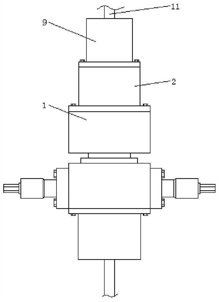
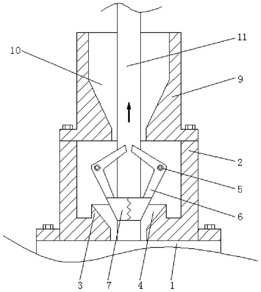
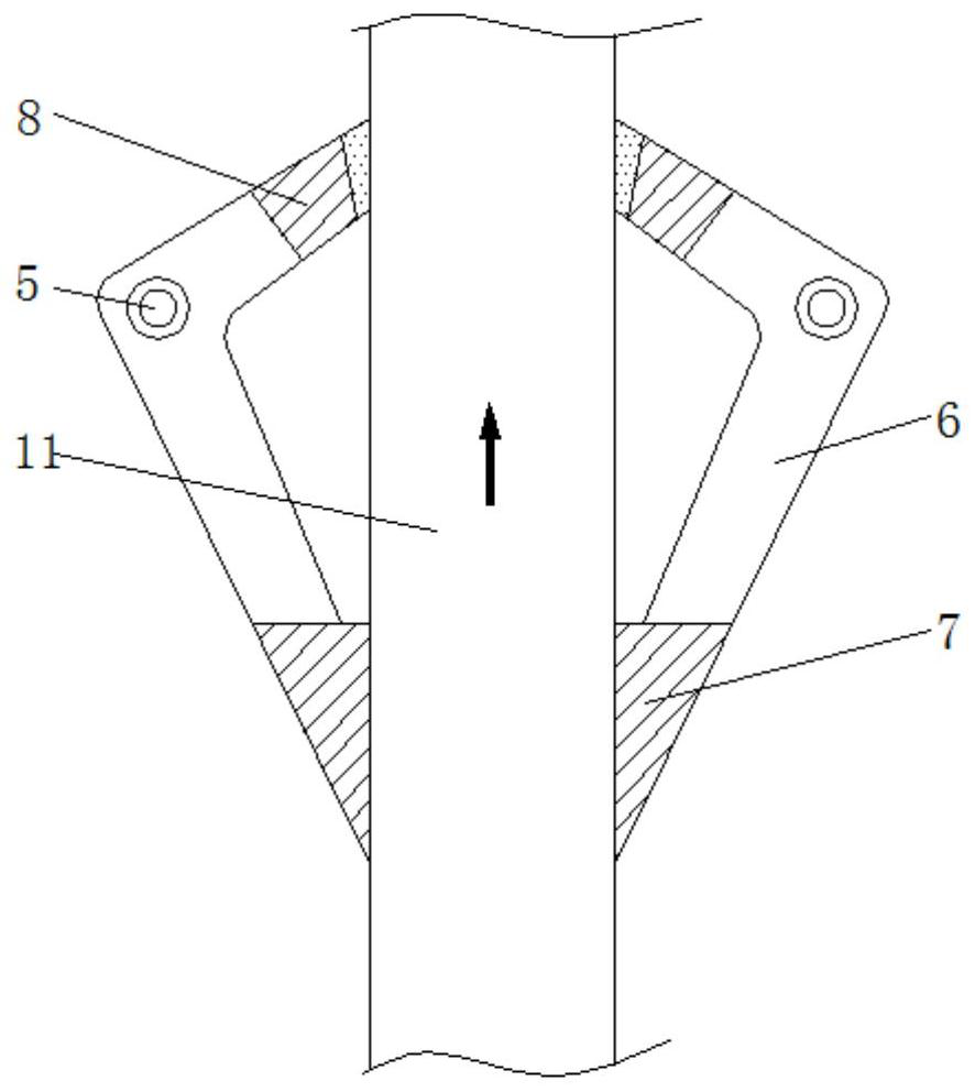
[0027] see figure 1 -7. A sucker rod blowout preventer, comprising an annular blowout preventer casing 1, the top of the annular blowout preventer casing 1 is provided with a sealing casing 2, and the bottom surface of the inner cavity of the sealing casing 2 is provided with There is a boss 3, the interior of the boss 3 is provided with a limit hole 4, the inner wall of the sealed housing 2 is provided with a fixed shaft 5, and the outer part of the fixed sha...


PUM


Abstract

The invention relates to the technical field of oil field mining equipment, and discloses a sucker rod blowout preventer which comprises an annular blowout preventer casing, the top of the annular blowout preventer casing is provided with a sealed casing, and the bottom surface of the inner cavity of the sealed casing is provided with a boss. Through the friction between scraping rubber and a sucker rod, upward acting force is provided for an upper arm when the sucker rod moves up, so that a connecting member rotates counterclockwise with a fixed shaft as a central shaft, and a lower arm drives the scraping rubber to be attached to the sucker rod so that the two pieces of scraping rubber are meshed on the outer portion of the sucker rod, and the inner surface of the scraping rubber is attached to the outer portion of the sucker rod. The sucker rod moves relative to the scraping rubber to scrap off crude oil on the outer portion of the sucker rod. Compared with the prior art, no artificial control is required, the acting force between the scraping rubber and the sucker rod is small, the abrasion speed of the sucker rod is reduced, and the problem that the crude oil moves out with the sucker rod, falls onto a well mouth and a site and pollutes the environment is solved.

Description

technical field [0001] The invention relates to the technical field of oil field exploitation equipment, in particular to a sucker rod blowout preventer. Background technique [0002] The blowout preventer is a device used to close the wellhead during oil well testing, workover, well completion and other operations in oil field construction. The formation fluid in the oil well is circulated to prevent well kicks and blowouts, causing safety accidents. According to different working principles, it can be divided into ram blowout preventer and annular blowout preventer. The annular blowout preventer is mainly composed of shell, top The cover, the rubber core and the piston are composed of four parts. Its working principle is to use the hydraulic pressure in the oil cylinder to push the piston to move upward, squeeze the rubber core, deform the rubber core to the center, close the oil well head, and lift the sucker rod At this time, by controlling the hydraulic pressure inside...

Claims


Application Information

Patent Timeline
Patent Type & Authority Patents(China)
IPC IPC(8): E21B33/06E21B37/02
CPCE21B33/06E21B37/02
Inventor 不公告发明人
Owner 广西北部湾粮油技术研究有限公司
Why Eureka
Try Eureka