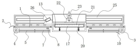
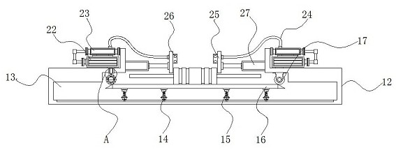
Lathe material receiving device with feeding and discharging functions and for electronic part machining

A technology of feeding device and spare parts, applied in the direction of manufacturing tools, metal processing, metal processing equipment, etc., can solve the problems of mixed diodes, affecting the quality of finished products, single function, etc. Small volume effect

Inactive Publication Date: 2021-02-05
深圳市辉迪机电科技有限公司
View PDF0 Cites 0 Cited by
  • Summary
  • Abstract
  • Description
  • Claims
  • Application Information

AI Technical Summary

Problems solved by technology

[0004] Aiming at the deficiencies of the prior art, the present invention provides a lathe receiving device with loading and unloading functions for processing electronic parts and components, which solves the above-mentioned problem in the background technology that the transfer of existing materials is mostly a conveyor belt with a single function. The diode can be transferred, but the size of the diode cannot be detected, and it is easy to cause unqualified diodes and qualified diodes to be mixed together for subsequent processing, thus affecting the quality of the finished product.

Method used


Image

  • Lathe material receiving device with feeding and discharging functions and for electronic part machining
  • Lathe material receiving device with feeding and discharging functions and for electronic part machining
  • Lathe material receiving device with feeding and discharging functions and for electronic part machining

Examples


Embodiment Construction

[0027] The following will clearly and completely describe the technical solutions in the embodiments of the present invention with reference to the accompanying drawings in the embodiments of the present invention. Obviously, the described embodiments are only some, not all, embodiments of the present invention.

[0028] In the description of the present invention, unless otherwise stated, the meaning of "plurality" is two or more; the terms "upper", "lower", "left", "right", "inner", "outer" , "front end", "rear end", "head", "tail", etc. indicate the orientation or positional relationship based on the orientation or positional relationship shown in the drawings, and are only for the convenience of describing the present invention and simplifying the description, rather than Indicates or implies that the device or element referred to must have a particular orientation, be constructed and operate in a particular orientation, and therefore should not be construed as limiting the...


PUM


Abstract

The invention discloses a lathe material receiving device with feeding and discharging functions and for electronic part machining, and relates to the technical field of electronic part machining. Thelathe material receiving device particularly comprises a conveying belt and a detection mechanism, and a first rubber arc piece is fixed to the left side of the upper surface of the conveying belt. Each feeding and discharging mechanism comprises a movable shaft, a first pull plate, an extension plate, a second pull plate, an adsorption magnet and an elastic electromagnet, wherein the extension plate is arranged in the first pull plate, a second rubber arc piece is arranged on the right side of the lower surface of the first pull plate and on the right side of the conveying belt, and the detection mechanism is arranged in the middle section of the conveying belt. According to the lathe material receiving device with the feeding and discharging functions and for electronic part machining,diodes roll on the surface of a detection induction plate so that the length and the diameter of the diodes can be detected, the unqualified diodes can be taken out in cooperation with an external mechanical claw, the situation that the unqualified diodes and the qualified diodes are mixed together for subsequent machining is avoided, and impact on finished product quality is avoided.

Description

technical field [0001] The invention relates to the technical field of electronic spare parts processing, in particular to a lathe material receiving device with loading and unloading functions for electronic spare parts processing. Background technique [0002] Diode is a common electronic component. It is cylindrical in shape and has pins connected at both ends. It is widely used in various electronic products. Diodes need to be continuously transferred to different processing lathes for processing during production and processing. , At this time, a material receiving device is required for transfer. [0003] Most of the existing material transposition is a conveyor belt, which has a single function and can only transport the diodes, and cannot detect the size of the diodes. It is easy to cause unqualified diodes and qualified diodes to be mixed together for subsequent processing, thereby affecting the finished product. quality. Contents of the invention [0004] Aimin...

Claims


Application Information

Patent Timeline
IPC IPC(8): B23B5/00B23B13/12B23Q7/03B23Q11/00B23Q17/20
CPCB23B5/00B23B13/123B23Q7/03B23Q11/0075B23Q17/20
Inventor 张绍辉李智鹏
Owner 深圳市辉迪机电科技有限公司
Why Eureka
Try Eureka