Light interior wall partition strip plate production equipment

A technology for production equipment and spacers, which is applied in the field of production equipment for lightweight interior wall spacers, and can solve problems such as unfavorable rapid production and large time spans

Inactive Publication Date: 2021-11-19
张永会
View PDF3 Cites 0 Cited by
  • Summary
  • Abstract
  • Description
  • Claims
  • Application Information

AI Technical Summary

Problems solved by technology

[0003] However, the existing equipment for spacers needs to cool the spacers naturally, and the time span is large, which is not conducive to the needs of rapid production. At the same time, the raw materials of the spacers are stirred and screened to prevent the damage caused by impurities. The partition board is not rigid enough, and the above problems cannot be effectively solved in the existing equipment, so we propose a light-weight interior wall partition board production equipment

Method used


Image

  • Light interior wall partition strip plate production equipment
  • Light interior wall partition strip plate production equipment
  • Light interior wall partition strip plate production equipment

Examples


Embodiment 1

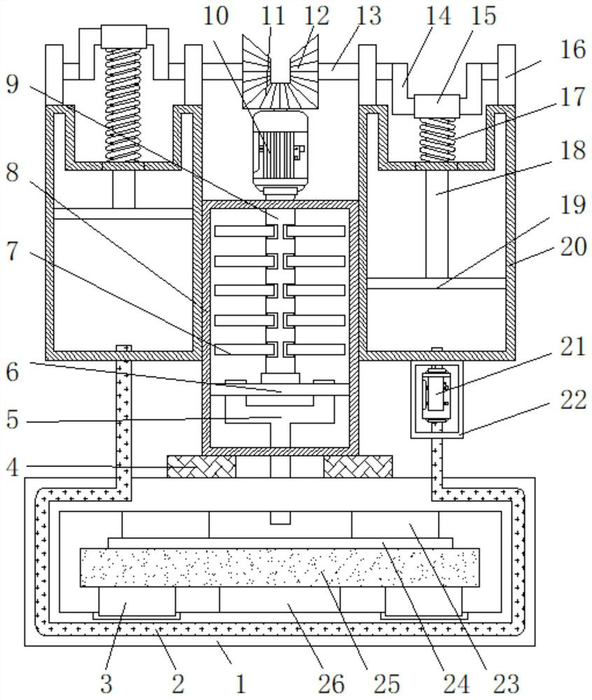
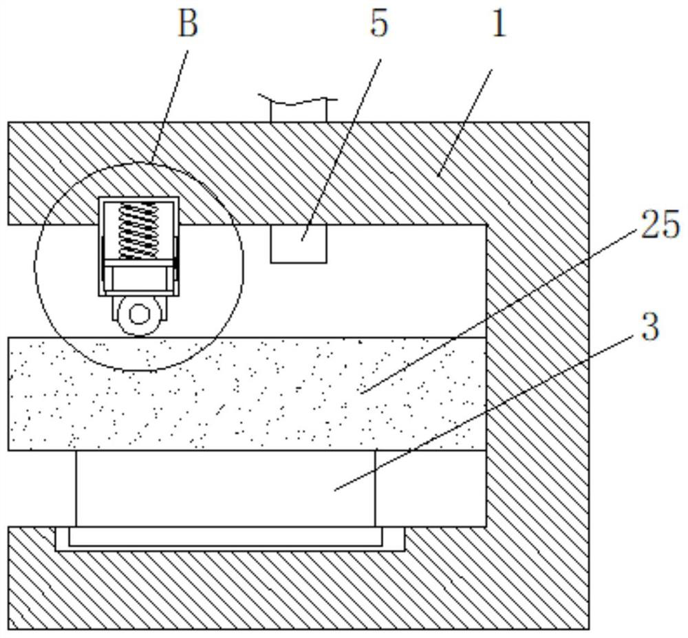
[0030] Embodiment 1: as figure 1 As shown, a kind of light-weight interior wall spacer panel production equipment that the present invention proposes comprises a first box body 1, and first fixing block 4 is welded on both sides of the top of the first box body 1, and the first fixing block 4 The top is welded with a second box body 8, the inner walls of both sides of the second box body 8 are welded with fixed plates 6, the top of the second box body 8 is fixedly connected with a motor 10, and the bottom output end of the motor 10 is welded to penetrate and extend to the second box body. The stirring roller 9 in the second casing 8, the outer ring of the stirring roller 9 is welded with a plurality of glue rods 7, and the stirring roller 9 is positioned at one end in the second casing 8 and is connected to the top of the fixed plate 6 for rotation;

Embodiment 2

[0031] Embodiment 2: as figure 1As shown, the top output end of the motor 10 is welded with a first bevel gear 11, both sides of the second box body 8 are welded with a third box body 20, and both sides of the top of the third box body 20 are welded with a stabilizing block 16, The sides of the stabilizing blocks 16 close to each other are rotatably connected to the crankshaft 14, the ends of the crankshafts 14 close to each other are welded with the rotating shaft 13, the ends of the rotating shaft 13 close to each other are welded with the second bevel gear 12, and the outer ring of the crankshaft 14 is sleeved with a sleeve 15. The bottom of the sleeve 15 is welded with a movable rod 18 that penetrates and extends into the third box body 20. The bottom of the sleeve 15 is welded with a first spring 17 sleeved on the outer ring of the movable rod 18. The first spring 17 is away from the One end of the sleeve pipe 15 is welded to the top of the third box body 20, and the end ...

Embodiment 3

[0032] Embodiment 3: as figure 1 , Figure 5 As shown, the bottom of the third box body 20 on the right is welded with a frame 22, and the top inner wall of the frame 22 is fixedly connected with a refrigerator 21, and the water inlet end of the refrigerator 21 runs through and extends into the third box body 20, and the refrigerator 21 The outlet end of the water outlet is sleeved with a condensation pipe 2 that penetrates and extends into the first box body 1. One end of the condensation pipe 2 located in the first box body 1 is socketed with the bottom of the third box body 20 on the left side. The first box body The top inner wall of 1 is welded with a fourth box body 23, the top inner wall of the fourth box body 23 is welded with a second spring 31, and the other end of the second spring 31 is welded with a sliding connection with the inner walls of both sides of the fourth box body 23. Plate 33, the side of the movable plate 33 away from the second spring 31 is welded w...


PUM


Abstract

The invention discloses light interior wall partition strip plate production equipment, and relates to the field of partition strip plate production. The problems that the cooling time of partition strip plate production is long, and the rigidity of a partition strip plate is affected due to many impurities in raw materials are solved. According to the scheme, the light interior wall partition strip plate production equipment comprises a first box body, first fixing blocks are welded to the two sides of the top of the first box body, a second box body is welded to the top of the first fixing block, fixing plates are welded to the inner walls of the two sides of the second box body, and a motor is fixedly connected to the top of the second box body. The equipment is reasonable in structural design, the density of partition strip plates is guaranteed by deeply processing raw materials of the partition strip plates, meanwhile, the formed partition strip plates are rapidly cooled, the rapid manufacturing effect is achieved, the partition strip plates are compacted and shaped, integrated operation is achieved, the working progress is accelerated, and meanwhile, the equipment is low in manufacturing cost, easy to operate, high in practicability and suitable for wide popularization.

Description

technical field [0001] The invention relates to the field of spacer board production, in particular to a production equipment for lightweight interior wall spacer boards. Background technique [0002] Lightweight partition board is a new type of energy-saving wall material. It is composed of harmless phosphogypsum, light steel slag, fly ash and other industrial waste residues. It is made of frequency conversion steam and pressurized. It looks like a hollow floor. , there are male and female falcon grooves on both sides. During installation, the male and female falcons can be assembled after being coated with a small amount of caulking mortar. It has the advantages of light weight, high strength, thermal insulation, sound insulation, fire prevention, and reduced wall cost. The inner layer is equipped with heat-insulating and sound-absorbing inorganic foam profiles or other heat-insulating materials in a reasonable layout. The wall panels are poured, leveled and scientifically...

Claims


Application Information

Patent Timeline
Patent Type & Authority Applications(China)
IPC IPC(8): B28B3/12B28B11/24B28B13/02B28C5/16
CPCB28B3/123B28B11/24B28B13/02B28C5/16
Inventor 张永会
Owner 张永会
Why Eureka
Try Eureka