Textile machinery supporting device

A technology of textile machinery and supporting devices, which is applied in the direction of textile, looms, mechanical equipment, etc. It can solve the problems of no shock-absorbing structure, the inability to deal with the dust of textile machinery, and the failure of textile machinery vibration, so as to achieve good filtration and shock resistance effect of effect

Inactive Publication Date: 2021-02-05
马鞍山迈若斯机器人科技有限公司
View PDF0 Cites 1 Cited by
  • Summary
  • Abstract
  • Description
  • Claims
  • Application Information

AI Technical Summary

Problems solved by technology

[0006] The existing design does not have a shock-absorbing structure, and the textile machinery is prone to malfunction due to vibration and cannot deal with the problem of dust generated when the textile machinery is working.

Method used


Image

  • Textile machinery supporting device
  • Textile machinery supporting device
  • Textile machinery supporting device

Examples


Embodiment 1

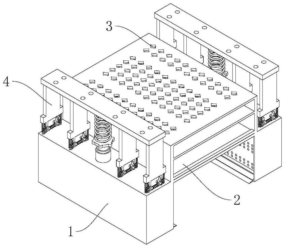
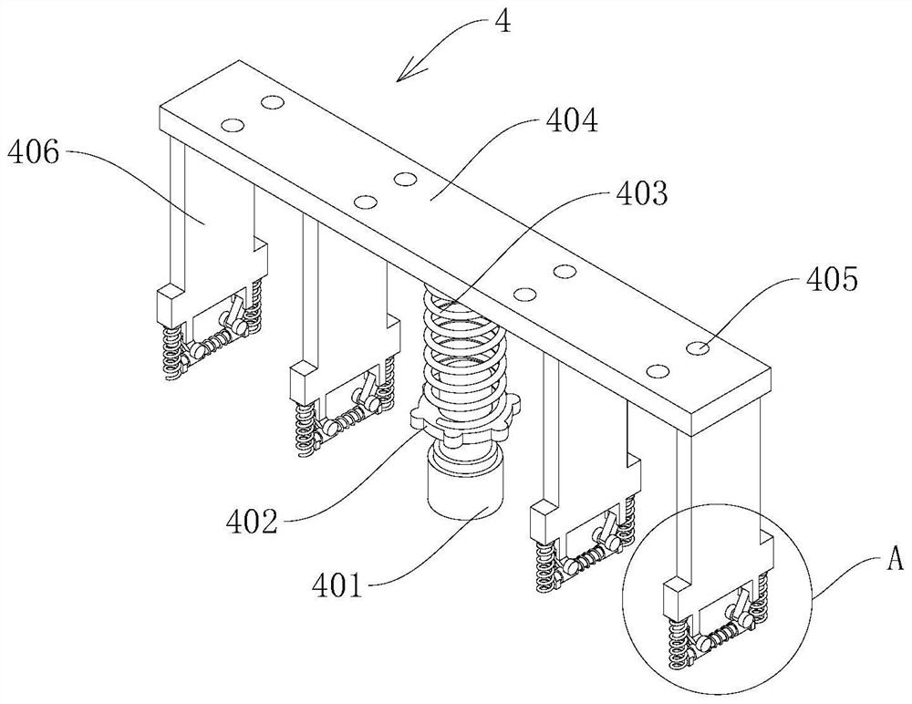
[0029] see Figure 1-4 , a textile machinery support device, including a support base 1 and a mounting frame 2, the mounting frame 2 is fixedly connected to the top of the support base 1, the top surface of the mounting frame 2 is provided with air holes 3, the top ends of the support base 1 It is connected with an adjustable shock-absorbing device 4, and the adjustable shock-absorbing device 4 includes a fixed rod 401. The fixed rod 401 is fixedly connected to the top surface of the support base 1. The fixed rod 401 is screw-connected with an adjustment disc 402, and the fixed rod 401 is also covered with Connected with a first damping spring 403, the bottom end of the first damping spring 403 is in contact with the adjustment plate 402, the top end of the first damping spring 403 is fixedly connected with the textile machine mounting plate 404, and the textile machine mounting plate 404 is provided with a mounting hole 405, the bottom surface of the textile machinery mountin...

Embodiment 2

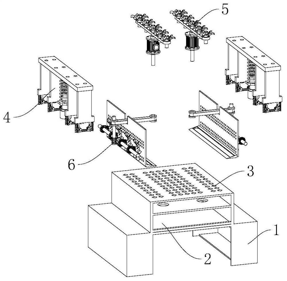
[0034] see Figure 5 , the difference with the basis of Embodiment 1 is that the drive cooling mechanism 5 includes a biaxial servo motor 501, the biaxial servo motor 501 is fixedly connected inside the installation frame 2, and the upper end output shaft of the biaxial servo motor 501 is fixed Connected with a driving shaft 502, the driving shaft 502 is fixedly connected with a drive gear 503, the two sides of the driving shaft 502 are provided with a driven shaft 504, the driven shaft 504 is rotatably connected to the mounting frame 2, and the driven shaft 504 is fixedly connected with The driven gear 505, the driving gear 503 and the driven gear 505 are meshed with a linkage chain 506, and the tops of the driving shaft 502 and the driven shaft 504 are fixedly connected with a cooling fan blade 507, and the cooling fan blade 507 is arranged on the top surface of the installation frame 2 Below the ventilation hole 3.

[0035] The driving heat dissipation mechanism 5 of the p...

Embodiment 3

[0037] see Image 6 , the difference with the basis of Embodiment 1 is that the linkage dust suction mechanism 6 also includes a first belt pulley 601 and a second belt pulley 602, and the first belt pulley 601 is fixedly connected to the output of the lower end of the double-axis servo motor 501 On the shaft, the second belt pulley 602 is rotatably installed inside the support base 1, the first belt pulley 601 and the second belt pulley 602 are connected with a linkage belt 603, and the bottom end of the second belt pulley 602 is fixedly connected with a worm 604, The worm 604 is meshed with the worm wheel 605 , the worm wheel 605 is fixedly connected to the linkage shaft 606 , and the two ends of the linkage shaft 606 are rotatably connected to the inner side wall of the support base 1 .

[0038] The linkage shaft 606 is fixedly connected with a first bevel gear 607, the first bevel gear 607 is meshed with the second bevel gear 608, and the second bevel gear 608 is fixedly c...


PUM


Abstract

The invention discloses a textile machinery supporting device, and belongs to the technical field of textile machinery. The textile machinery supporting device comprises a supporting base and a mounting frame, wherein the mounting frame is fixedly connected to the top end of the supporting base, air holes are formed in the top face of the mounting frame, adjusting damping devices are connected tothe two ends of the top end of the supporting base, and each adjusting damping device comprises a fixing rod which is fixedly connected to the top face of the supporting base; an adjusting disc is spirally connected to the fixing rod, the fixing rod is further sleeved with a first damping spring, an auxiliary supporting plate is fixedly connected to the bottom face of the textile machine mountingplate, and an auxiliary damping mechanism is connected to the bottom end of the auxiliary supporting plate; and a driving heat dissipation mechanism is connected to the side wall of the mounting frame, and a linkage dust collection mechanism is mounted in the mounting frame and the supporting base. According to the textile machinery supporting device, the problems that because a damping structureis not arranged in the existing design, textile machinery is prone to failure due to vibration, and raised dust generated when the textile machinery works cannot be treated are effectively solved.

Description

technical field [0001] The invention relates to the technical field of textile machinery, in particular to a textile machinery supporting device. Background technique [0002] Textile machinery is all kinds of mechanical equipment needed to process natural fibers or chemical fibers into textiles. Although the machinery for producing chemical fibers includes a variety of chemical machinery, it is now considered an extension of textile machinery and belongs to textile machinery in a broad sense. The processes required to process different fibers such as cotton, hemp, silk, wool, etc. into textiles are not the same, and some are completely different, so the machines required are also various and varied. Textile machinery is usually classified according to the production process and can be divided into spinning equipment, weaving equipment, printing and dyeing equipment, finishing equipment, chemical fiber spinning equipment, reeling equipment and non-woven fabric equipment. S...

Claims


Application Information

Patent Timeline
Patent Type & Authority Applications(China)
IPC IPC(8): F16F15/067D03D49/02D03J1/00
CPCD03D49/025D03J1/002F16F15/067
Inventor 邵伟伟盛娜
Owner 马鞍山迈若斯机器人科技有限公司
Why Eureka
Try Eureka