
Adjustable detection device for comprehensive automation equipment

A technology of automation equipment and detection device, applied in the direction of measurement device, transportation and packaging, measurement instrument components, etc., can solve the problems of inconvenient detection, machine wear, heavy workload, etc. The effect of speeding up efficiency

Inactive Publication Date: 2021-02-05
江苏枂硕电子科技有限公司
View PDF0 Cites 1 Cited by
  • Summary
  • Abstract
  • Description
  • Claims
  • Application Information

AI Technical Summary

Problems solved by technology

[0002] With the development and construction of science and technology, electrical automation equipment has largely replaced manpower in industrial operations. People have relied heavily on electrical automation equipment, and it is also an indispensable part of people's lives. However, electrical Automation will also have certain problems over time, such as the aging of wires and cables, and abnormalities in machine wear. Therefore, people often use workbenches for electrical automation equipment testing, but the uneven height of the testing staff is inconvenient for testing. However, traditional testing devices for electrical automation equipment usually use hand-held detectors to detect factors such as the performance and quality of electrical automation equipment. The detection method has defects such as difficult positioning, low detection efficiency, heavy workload, and long time consumption. The efficiency and accuracy of detection, for this reason, we propose an adjustable detection device for comprehensive automatic equipment

Method used


Image

  • Adjustable detection device for comprehensive automation equipment
  • Adjustable detection device for comprehensive automation equipment
  • Adjustable detection device for comprehensive automation equipment

Examples


Embodiment Construction

[0021] The following will clearly and completely describe the technical solutions in the embodiments of the present invention with reference to the accompanying drawings in the embodiments of the present invention. Obviously, the described embodiments are only some, not all, embodiments of the present invention. Based on the embodiments of the present invention, all other embodiments obtained by persons of ordinary skill in the art without making creative efforts belong to the protection scope of the present invention.

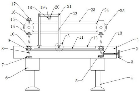
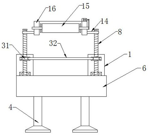
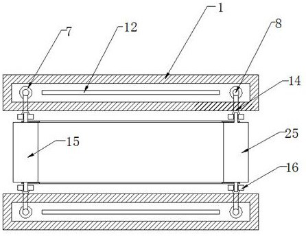
[0022] see figure 1 , the present invention provides a technical solution: an adjustable detection device for comprehensive automation equipment, including a support bar 1, two sets of support bars 1 are arranged in parallel in front and rear, and the left and right ends of the lower end surface of the support bar 1 are fixed Be connected with support block 6, support block 6 lower end front and back both sides are provided with support column 4, support cross...


PUM


Abstract

The invention discloses an adjustable detection device for comprehensive automatic equipment in the technical field of detection equipment, which comprises two groups of supporting cross rods arrangedin parallel front and back, wherein supporting blocks are fixedly connected to the left and right ends of the lower end surface of each supporting cross rod, supporting columns are arranged on the front and back sides of the lower end surface of each supporting block, an inner cavity of the supporting cross rod is hollow, supporting bearings are arranged on the left side and the right side of thebottom end face of the inner cavity of the supporting cross rod, threaded rods are fixedly connected to inner rings of the supporting bearings and penetrate through the upper end face of the supporting cross rod to the upper portion of the supporting cross rod, first belt wheels and second belt wheels are fixedly connected to the outer walls of the lower portions of the threaded rods on the frontside, a belt is fixedly connected between the two sets of second belt wheels, and a driven bevel gear is fixedly connected to the outer wall of the lower portion of the threaded rod on the right portion of the front side. The device is simple in structure and convenient to operate, and the detection speed and effect are improved.

Description

technical field [0001] The invention relates to the technical field of detection equipment, in particular to an adjustable detection device for comprehensive automatic equipment. Background technique [0002] With the development and construction of science and technology, electrical automation equipment has largely replaced manpower in industrial operations. People have relied heavily on electrical automation equipment, and it is also an indispensable part of people's lives. However, electrical Automation will also have certain problems over time, such as the aging of wires and cables, and abnormalities in machine wear. Therefore, people often use workbenches for electrical automation equipment testing, but the uneven height of the testing staff is inconvenient for testing. However, traditional testing devices for electrical automation equipment usually use hand-held detectors to detect factors such as the performance and quality of electrical automation equipment. The dete...

Claims


Application Information

Patent Timeline
IPC IPC(8): G01D21/00G01D11/30B65G41/00B65G15/00
CPCB65G15/00B65G41/003G01D11/30G01D21/00
Inventor 程小龙常耀方
Owner 江苏枂硕电子科技有限公司
Learn More