Valve detection method and detection equipment

A detection method and technology of detection equipment, which are applied in mechanical valve testing, workpiece clamping devices, workbenches, etc., can solve the problems such as the inability to adjust the clamping force of the valve detection device and the inability to adapt to different requirements of the clamping force, and achieve a simple structure. , Reliable clamping, easy adjustment effect

Active Publication Date: 2021-02-05
浙江科科检测科技有限公司
View PDF9 Cites 0 Cited by
  • Summary
  • Abstract
  • Description
  • Claims
  • Application Information

AI Technical Summary

Problems solved by technology

[0005] The clamping force of the above-mentioned valve detection device cannot be adjusted, so it cannot adapt to the different requirements for clamping force of valves of different specifications

Method used


Image

  • Valve detection method and detection equipment
  • Valve detection method and detection equipment
  • Valve detection method and detection equipment

Examples


Embodiment 1

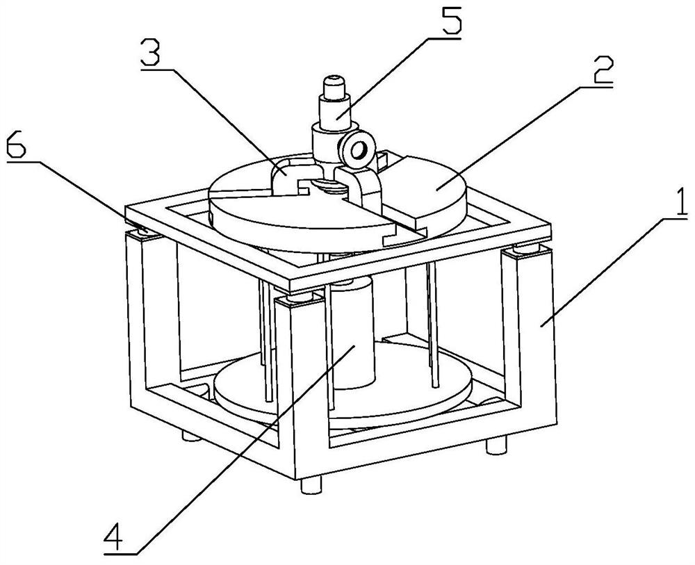
[0035] Embodiment 1 Overhead valve detection equipment

[0036] The upper-top valve detection device includes a clamping table, a valve clamping device and a control system arranged on the clamping table, and the clamping table includes a clamping frame 1 and a fixing plate 2 arranged on the clamping frame 1, so The valve clamping device includes several clamps 3 evenly arranged on the fixed plate 2 and a driving device 4 for applying and adjusting the clamping force. The clamping frame 1 is a rectangular frame, including an upper frame and a lower frame, and four sensors 6 for weighing the valve 5 to be tested are arranged between the upper frame and the lower frame; the clamp 3 is a jaw type clamp 3, The fixed plate 2 is provided with a radial chute, and the jaw type clamp 3 is slid in the chute; the clamping frame 1 is fixedly provided with a mounting plate, and the bottom of the driving device 4 is set on the mounting plate And the piston rod is vertically upward, the upp...

Embodiment 2

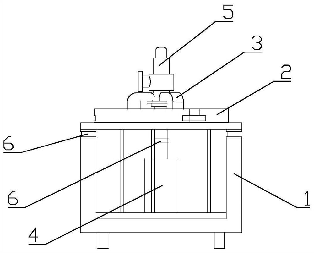
[0039] Embodiment 2 Push-down valve detection equipment 1

[0040]The push-down valve detection device includes a clamping table, a valve clamping device and a control system arranged on the clamping table, and the clamping table includes a clamping frame 1 and a fixing plate 2 arranged on the clamping frame 1. The valve clamping device includes several clamps 3 evenly arranged on the fixed plate 2 and a driving device 4 for applying and adjusting the clamping force. The clamping frame 1 is a rectangular frame, including an upper frame and a lower frame, and four sensors 6 for weighing the valve 5 to be tested are arranged between the upper frame and the lower frame; the clamp 3 is a jaw type clamp 3, The slide bar is slidably arranged in the axial installation hole of the fixed plate 2, and the lower end of the slide bar is fixed with a moving plate; the drive device 4 is vertically arranged in the clamping frame 1 and the piston rod is vertically downward, so that The lower...

Embodiment 3

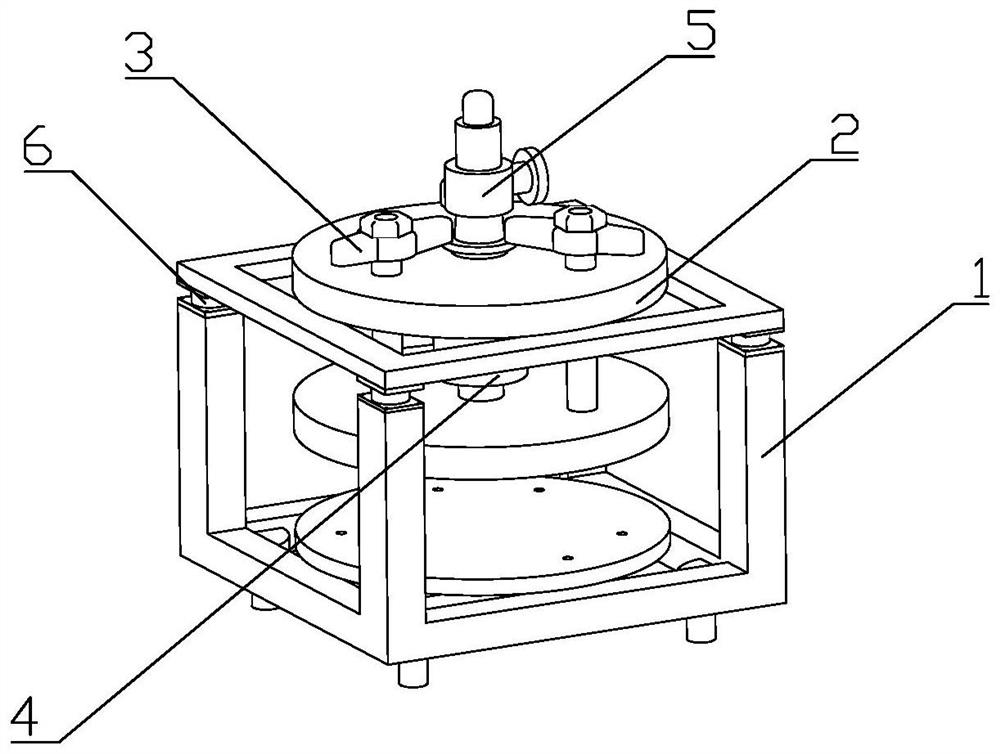
[0043] Embodiment 3 Push-down valve detection equipment 2

[0044] The push-down valve detection device includes a clamping table, a valve clamping device and a control system arranged on the clamping table, and the clamping table includes a clamping frame 1 and a fixing plate 2 arranged on the clamping frame 1. The valve clamping device includes several clamps 3 evenly arranged on the fixed plate 2 and a driving device 4 for applying and adjusting the clamping force. The clamping frame 1 is a rectangular frame, including an upper frame and a lower frame, and four sensors 6 for weighing the valve 5 to be tested are arranged between the upper frame and the lower frame; the clamp 3 is a lever clamp 3, hinged On the mounting seat, the fixed plate 2 is provided with a radial chute, and the mounting seat is slid in the chute; the driving device 4 is vertically arranged on the mounting seat and the piston rod is vertically upward, and the lever type One end of the clamp 3 is hinged...


PUM


Abstract

The invention belongs to the technical field of valve detection, and relates to a valve detection method. A to-be-detected valve is clamped by a valve clamping device on a clamping table, the method comprises the adjustment of the clamping force of the to-be-detected valve, and the method comprises the following steps of: weighing the to-be-detected valve to obtain the gravity G of the valve; calculating the adjusting force F=P*S corresponding to the setting pressure according to the flow channel sectional area S of the valve and the setting pressure P; and calculating the clamping force according to the valve gravity G, the adjusting force F and the sealing coefficient K; the invention further provides valve detection equipment, the detection equipment comprises a clamping table and a valve clamping device arranged on the clamping table, the clamping table comprises a clamping frame and a fixing plate arranged on the clamping frame, and the valve clamping device comprises a clamp arranged on the fixing plate and a driving device for applying and adjusting clamping force. According to the valve detection method and detection equipment provided by the invention, the clamping force can be adjusted for valves of different specifications.

Description

technical field [0001] The invention belongs to the technical field of valve detection, and relates to a valve detection method and detection equipment. Background technique [0002] After the safety valve is assembled, it is necessary to test and verify the opening pressure value and sealing performance of the valve. The above tests are completed by valve testing equipment, and a clamping device is required to clamp the valve to be tested during the test. Since the valves have different specifications, the clamping force required for the valves of different specifications is not the same. When the clamping force is too small, the valve to be tested will loosen during the test, which will affect the accuracy of the test and the smooth progress of the test; when the clamping force is too large, the valve will be easily damaged. [0003] Chinese invention patent application CN 108195515 A discloses a valve testing machine, which includes a test bench and a control system. R...

Claims


Application Information

Patent Timeline
IPC IPC(8): G01M13/003B25H1/10B25B11/00
CPCG01M13/003B25H1/10B25B11/00
Inventor 曹亮李国良
Owner 浙江科科检测科技有限公司
Why Eureka
Try Eureka