Single exposure phase recovery imaging device and imaging method

A phase recovery and imaging device technology, applied in the field of laser coherent diffraction imaging, can solve problems such as time-consuming, affecting imaging quality, mutual interference, etc., and achieve the effects of low cost, increased imaging field of view, and fast convergence speed

Inactive Publication Date: 2021-02-05
SHANGHAI INST OF OPTICS & FINE MECHANICS CHINESE ACAD OF SCI
View PDF5 Cites 3 Cited by
  • Summary
  • Abstract
  • Description
  • Claims
  • Application Information

AI Technical Summary

Problems solved by technology

Among them, the grating will interfere with each other between adjacent beams during the process of splitting light, which will affect the imaging quality.
When using a phase plate with a known distribution for a single exposure, the phase plate needs to be rigorously calibrated, which takes a lot of time

Method used


Image

  • Single exposure phase recovery imaging device and imaging method
  • Single exposure phase recovery imaging device and imaging method
  • Single exposure phase recovery imaging device and imaging method

Examples


Embodiment

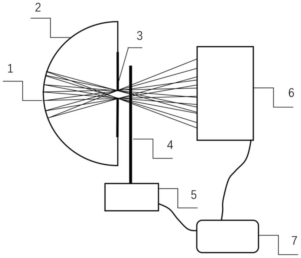
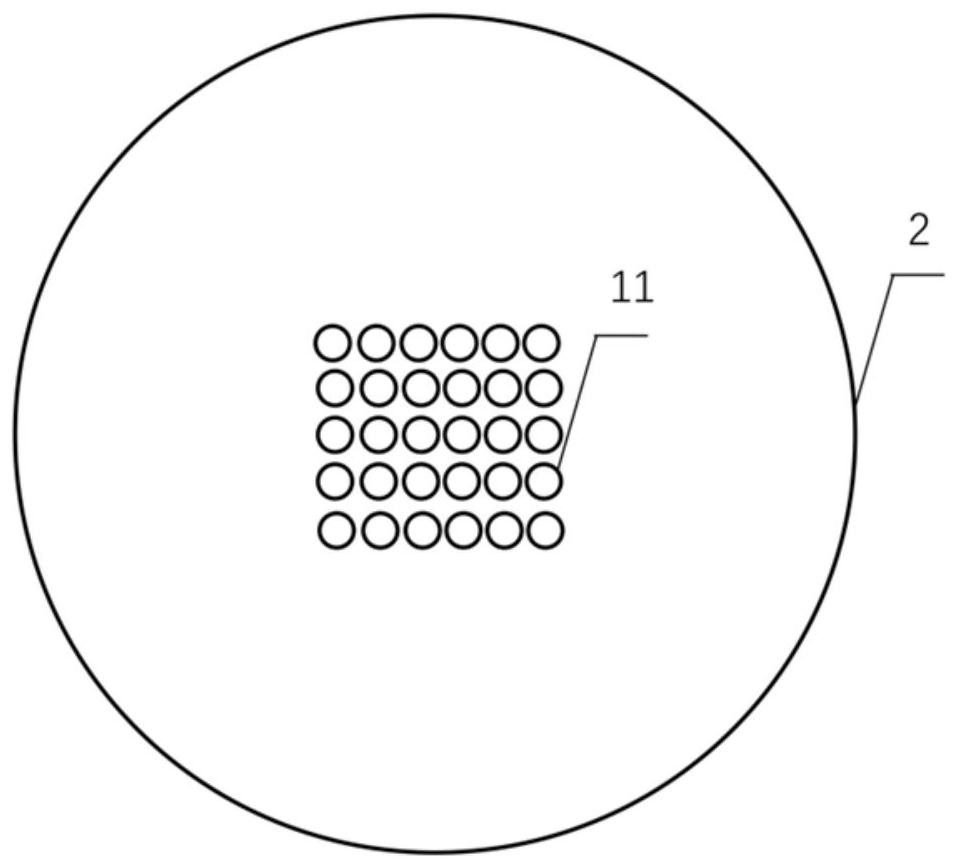
[0041] Described light source 1 is LD light source, and center wavelength is 638 nanometers,

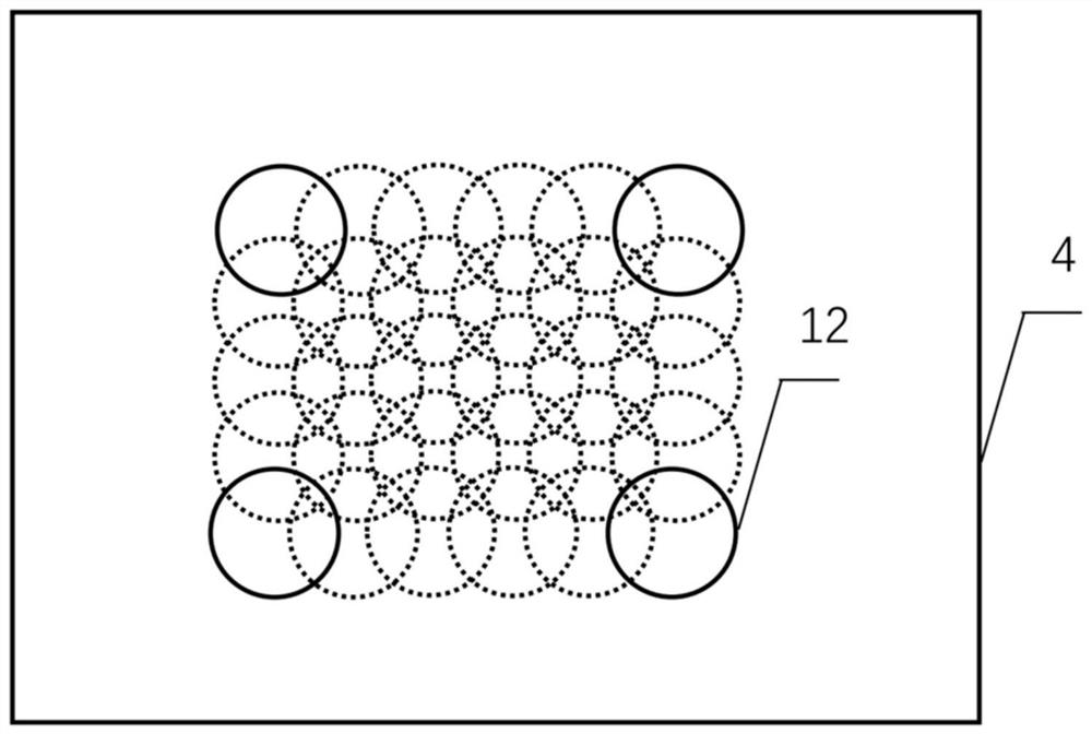
[0042] The hemispherical shell 2 is used to fix the LD light source 1, and the small hole 3 is placed at the center of the hemispherical shell 2. The sample 4 is placed on the two-dimensional translation platform 5, the sample 4 is placed on the two-dimensional translation platform 5, and the two-dimensional translation platform 5 is controlled by the computer 7, so The above-mentioned two-dimensional photodetector 6 is a CCD, which collects and records the diffraction spot of the sample 4 . The light beams of the 30 LD light sources 1 all point to the center of the sphere and pass through the small hole 3, pass through the sample 4, and form images on the CCD surface of the two-dimensional photodetector 6;

[0043] A method for imaging a sample using the above-mentioned fast phase recovery imaging device, the imaging method includes the following steps:

[0044]1) The two-dimensio...


PUM

PropertyMeasurementUnit
wavelengthaaaaaaaaaa

Abstract

The invention relates to a single exposure phase recovery imaging device comprising an LD light source, a hemispherical shell, a small hole, a sample, a two-dimensional displacement platform, a two-dimensional photoelectric detector, a computer and data acquisition and processing software; the imaging method comprises the following steps: moving a sample through the two-dimensional displacement platform, and calibrating an illumination light array to obtain complex amplitude distribution of each illumination light beam; and recording a diffraction pattern containing 30 sub-diffraction spots byusing a two-dimensional photoelectric detector, and recovering the complex amplitude distribution of the sample. The device is simple in structure, low in manufacturing cost and short in data acquisition time, and the phase recovery algorithm has the characteristics of high convergence speed, high imaging measurement precision and the like.

Description

technical field [0001] The invention relates to laser coherent diffraction imaging, in particular to a single-exposure phase recovery imaging device and imaging method. Background technique [0002] In recent years, computational optical imaging technology has been developed rapidly. As an important branch, phase recovery imaging technology based on stacked diffraction imaging (PIE) has the characteristics of high resolution, large field of view, and high imaging accuracy. It has attracted extensive attention from scholars and has been applied in many fields, such as biological microscopic imaging, stress detection in glass, and measurement of multi-wavelength composite light fields. Usually, in order to collect more data, obtain a larger field of view and higher imaging accuracy, it is necessary to scan the sample at multiple points through the translation device, which increases the data acquisition time. In order to shorten the data collection time and adapt to more dyna...

Claims


Application Information

Patent Timeline
Patent Type & Authority Applications(China)
IPC IPC(8): G01N21/47
CPCG01N21/4788
Inventor 刘诚昌成成陶华潘兴臣朱健强
Owner SHANGHAI INST OF OPTICS & FINE MECHANICS CHINESE ACAD OF SCI
Why Eureka
Try Eureka