Imaging lens, camera module and electronic equipment

A technology of imaging lens and camera module, which is applied in the direction of optical components, optics, instruments, etc., can solve the problems of lens focal length limitation and difficult demand, and achieve the effect of shortening the lateral distance, saving space, and increasing the cost of the spacer

Pending Publication Date: 2021-02-05
JIANGXI JINGCHAO OPTICAL CO LTD
View PDF0 Cites 2 Cited by
  • Summary
  • Abstract
  • Description
  • Claims
  • Application Information

AI Technical Summary

Problems solved by technology

[0003] Usually the mobile phone camera is placed perpendicular to the back of the mobile phone, that is, the CMOS (complementary metal oxide semiconductor) sensor is parallel to the back of the mobile phone, so that the focal length of the lens is limited by the thickness of the mobile phone
In addition, the current zoom lens cannot achieve long-focus shooting on the premise of ensuring the light weight and ultra-thinness of the mobile phone, which is difficult to meet the market demand

Method used


Image

  • Imaging lens, camera module and electronic equipment
  • Imaging lens, camera module and electronic equipment
  • Imaging lens, camera module and electronic equipment

Examples


Embodiment 1

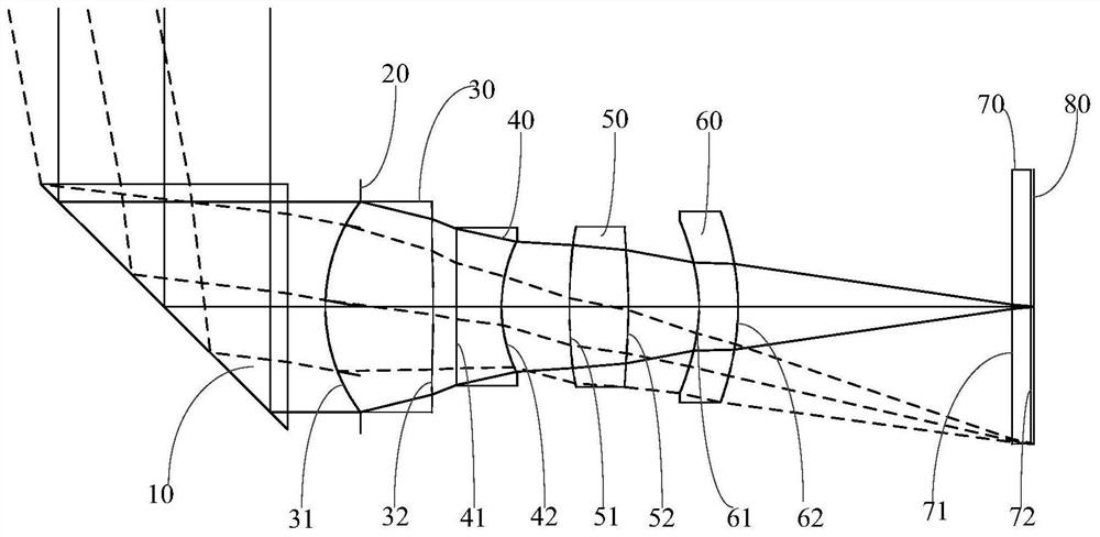
[0050] see figure 1 and figure 2 as shown, figure 1 The solid line through the lens indicates the central field of view, and the dashed line through the lens indicates the 1.0 field of view. According to Embodiment 1 of the present invention, an imaging lens is provided, and the imaging lens includes a prism 10, a first lens 30, a second lens 40, a third lens 50, and a fourth lens 60 arranged in sequence from the object side to the image side .

[0051] Wherein, the prism 10 is in the shape of a right triangle, the hypotenuse of the right triangle is set away from the first lens 30, and the two right angles of the right triangle are respectively set parallel to the optical axis and perpendicular to the optical axis, the prism 10 can make light deflection, and can form a folded periscope structure with the first lens 30, the second lens 40, the third lens 50 and the fourth lens 60, which can effectively utilize the space for installing the structure of the imaging lens and ...

Embodiment 2

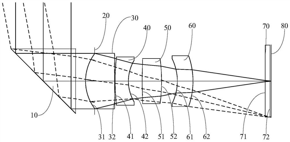
[0077] see image 3 with Figure 4 as shown, image 3 The solid line through the lens indicates the central field of view, and the dashed line through the lens indicates the 1.0 field of view. According to Embodiment 2 of the present invention, an imaging lens is provided, the structure of the imaging lens is basically the same as that in Embodiment 1, the difference is:

[0078] The object side surface 41 of the second lens 40 in this embodiment is convex at the optical axis and at the circumference.

[0079] The object side surface 51 of the third lens 50 is concave at the circumference.

[0080] The imaging lens in this embodiment satisfies the following conditional formula:

[0081] 0.4mm

[0082] 1.0

[0083] 1.51.6mm;

[0084] 2.0

[0085] 1.0mm<(T12+T23+T34)=1.866mm<3.0mm;

[0086] 0.05

[0087] 4

[0088] 5.5

[0089] Table 3 is a characterist...

Embodiment 3

[0099] see Figure 5 with Image 6 as shown, Figure 5 The solid line through the lens indicates the central field of view, and the dashed line through the lens indicates the 1.0 field of view. According to Embodiment 3 of the present invention, an imaging lens is provided, the structure of the imaging lens is basically the same as that in Embodiment 1, the difference is:

[0100] The object side surface 41 of the second lens 40 in this embodiment is convex at the optical axis and at the circumference.

[0101] The imaging lens in this embodiment satisfies the following conditional formula:

[0102] 0.4mm

[0103] 1.0

[0104] 1.51.6mm;

[0105] 2.0

[0106] 1.0mm<(T12+T23+T34)=1.448mm<3.0mm;

[0107] 0.05

[0108] 4

[0109] 5.5

[0110] Table 5 is a characteristic table of the imaging lens of this embodiment, wherein each data is obtained by using v...


PUM


Abstract

The invention discloses an imaging lens, a camera module and electronic equipment. The imaging lens comprises a prism, a first lens, a second lens, a third lens and a fourth lens which are sequentially arranged from the object side to the image side. The imaging lens satisfies the conditional expression that 0.4 mm<ET12+ ET23+ET34<2.5 mm, wherein ET12 is the distance from the maximum effective aperture of the image side surface of the first lens to the maximum effective aperture of the object side surface of the second lens on the optical axis, ET23 is the distance from the maximum effective aperture of the image side surface of the second lens to the maximum effective aperture of the object side surface of the third lens on the optical axis, and ET34 is the distance from the maximum effective aperture of the image side surface of the third lens to the maximum effective aperture of the object side surface of the fourth lens on the optical axis. The imaging lens achieves the long-focuscharacteristic, is short in transverse distance, and can meet the light and thin requirements of a cellphone.

Description

technical field [0001] The invention relates to the technical field of optical imaging, in particular to an imaging lens, a camera module and electronic equipment. Background technique [0002] In recent years, zoom lenses have become more and more popular among mobile phone terminal manufacturers and consumers, and imaging lenses can be a solution to the bulky optical zoom lens and are not easy to miniaturize. Imaging lenses are the key factor to increase the zoom factor of mobile phone cameras , whose special design makes it possible to realize a telephoto lens accommodated in a smartphone. Smartphones are becoming thinner and lighter, and to obtain telephoto features, the total optical length will be correspondingly longer, but limited by the limited thickness of mobile phones, so periscope mobile phone lenses have emerged. [0003] Usually the mobile phone camera is placed perpendicular to the back of the mobile phone, that is, the CMOS (Complementary Metal Oxide Semico...

Claims


Application Information

Patent Timeline
Patent Type & Authority Applications(China)
IPC IPC(8): G02B13/00G02B13/18
CPCG02B13/004G02B13/0065
Inventor 邹金华杨健李明
Owner JIANGXI JINGCHAO OPTICAL CO LTD
Why Eureka
Try Eureka