Power supply device
A technology of power supply device and control device, which is applied in the direction of circuit device, emergency power supply arrangement, output power conversion device, etc. It can solve the problems such as inability to switch off and achieve the effect of reducing surge voltage
- Summary
- Abstract
- Description
- Claims
- Application Information
AI Technical Summary
Problems solved by technology
Method used
Image


Examples
Embodiment approach 1
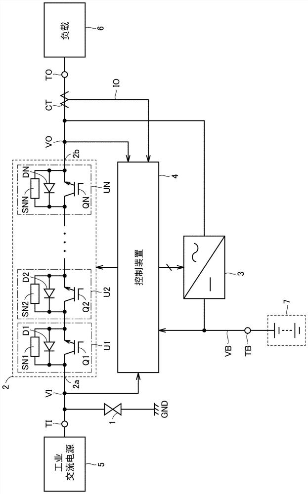
[0026] figure 1 It is a circuit block diagram showing the configuration of the uninterruptible power supply device according to the first embodiment. The uninterruptible power supply device supplies three-phase AC power to the load. In order to simplify the drawings and descriptions, the figure 1 Only the part associated with one is shown. In addition, such an uninterruptible power supply device is also called an instantaneous compensation device.
[0027] exist figure 1 Among them, the uninterruptible power supply device includes an AC input terminal TI, an AC output terminal TO, a battery terminal TB, a surge absorber 1 , a switch 2 , a current detector CT, a bidirectional converter 3 , and a control device 4 .
[0028] The AC input terminal TI receives the AC voltage VI of the commercial frequency from the commercial AC power supply 5 . The instantaneous value of the AC input voltage VI is detected by the control device 4 . The control device 4 determines whether or no...
Embodiment approach 2
[0102] Figure 9 It is a circuit block diagram showing main parts of an uninterruptible power supply device according to Embodiment 2 of the present invention, and is the same as Figure 4 Comparison chart. refer to Figure 9 The difference between this uninterruptible power supply device and the uninterruptible power supply device of Embodiment 1 is that the control unit 12 is replaced by the control unit 50 . In the control unit 50 , the delay circuit 20 of the control unit 12 is replaced by a zero-point detector 51 and an OR gate 52 .
[0103] Zero point detector 51 is in power failure detector 11 ( image 3 ) is activated when the output signal PC is "L" level, based on the current detector CT ( figure 1 ) output signal, detect the zero point of the AC output current IO, and output the signal DT representing the detection result. At the zero point of the AC output current IO, the instantaneous value of the AC output current IO becomes 0A.
[0104] When signal PC is a...
PUM
 Abstract
Description
Claims
Application Information
 - Generate Ideas
- Intellectual Property
- Life Sciences
- Materials
- Tech Scout
- Unparalleled Data Quality
- Higher Quality Content
- 60% Fewer Hallucinations
Browse by: Latest US Patents, China's latest patents, Technical Efficacy Thesaurus, Application Domain, Technology Topic, Popular Technical Reports.
© 2025 PatSnap. All rights reserved.Legal|Privacy policy|Modern Slavery Act Transparency Statement|Sitemap|About US| Contact US: help@patsnap.com