Knob assembly and cooking utensil
A technology of cooking utensils and knobs, which is applied in the field of cooking, and can solve problems such as no button feel, easy misuse of soup, and inability to adjust heating power in time
- Summary
- Abstract
- Description
- Claims
- Application Information
AI Technical Summary
Problems solved by technology
Method used
Image

Examples
Embodiment 1
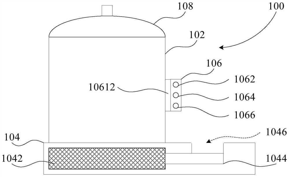
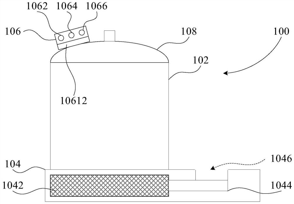
[0057] Such as figure 1 with figure 2 As shown, the knob assembly of an embodiment of the present invention includes: a magnetic control knob 106, the magnetic control knob 106 can be adsorbed and assembled on the magnetic part of the pot body 102; The temperature sensor 10612 is configured to detect the cooking temperature of the pot body 102 , and data interaction between the temperature sensor 10612 and the magnetic control knob 106 is possible.
[0058] In this technical solution, the magnetic control knob 106 and the magnetic part are adsorbed and assembled, and the area where the magnetic control knob 106 is in contact with the pot body 102 is provided with a temperature sensor 10612, and the temperature sensor 10612 can directly contact and detect the cooking temperature of the pot body 102, Not only the reliability, accuracy and timeliness of detecting the cooking temperature are improved, but also the reliability of heating power adjustment based on the cooking temp...
Embodiment 2
[0085] The hob 104 is provided with a position for placing the magnetic control knob 106, that is, the magnetic control knob placement position 1046. The magnetic control knob 106 is placed in the magnetic control knob placement position 1046, and the power is adjusted by rotating the magnetic control knob 106.
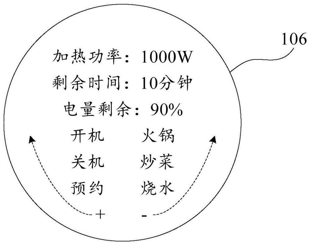
[0086] The prompt module 1068 of the magnetic control knob 106 can display: heating power, remaining time, remaining power, power on, power off, appointment, hot pot, cooking and boiling water, etc., but not limited thereto, and realizes the simplification of the touch panel.
[0087] The user touches the magnetic control knob 106 to start the machine, and after setting the cooking function and target heating power, the user puts the magnetic control knob 106 on the magnetic part of the pot body 102 to measure and control the temperature.
[0088] Functions such as power-on and power-off can also be placed on the touch panel, and the magnetic control knob 106 provides ...
Embodiment 3
[0090] Such as Figure 4 As shown, the magnetic control knob 106 is provided with a receiving part 1064, and is coupled with the transmitting part on the hob 104 to realize the wireless charging function.
[0091] When the magnetic control knob 106 is placed in the magnetic control knob position 1046, wireless charging can be performed at the same time. After the wireless charging is completed, the prompt module 1068 of the magnetic control knob 106 prompts the user that the wireless charging is completed.
[0092] After the wireless charging is completed, and the user completes the setting of the heating power, the user is reminded to place the knob on the temperature measurement part.
[0093] When the magnetic control knob 106 is placed at the position 1046 of the magnetic control knob, the wireless communication module stops sending and receiving data commands. The signal from the magnetic control knob 106 adjusts the heating power of the magnetic induction coil 1042 . A...
PUM
 Abstract
Description
Claims
Application Information
 - R&D
- Intellectual Property
- Life Sciences
- Materials
- Tech Scout
- Unparalleled Data Quality
- Higher Quality Content
- 60% Fewer Hallucinations
Browse by: Latest US Patents, China's latest patents, Technical Efficacy Thesaurus, Application Domain, Technology Topic, Popular Technical Reports.
© 2025 PatSnap. All rights reserved.Legal|Privacy policy|Modern Slavery Act Transparency Statement|Sitemap|About US| Contact US: help@patsnap.com