Mining coal crusher

A coal crusher and mining technology, applied in application, use of liquid separation agent, food science, etc., can solve problems such as inability to crush coal

Inactive Publication Date: 2021-02-09
曹丹
View PDF7 Cites 0 Cited by
  • Summary
  • Abstract
  • Description
  • Claims
  • Application Information

AI Technical Summary

Problems solved by technology

However, it cannot crush the composite coal that is coal on the outside and rock on the inside while reducing dust.

Method used


Image

  • Mining coal crusher
  • Mining coal crusher
  • Mining coal crusher

Examples


specific Embodiment approach 1

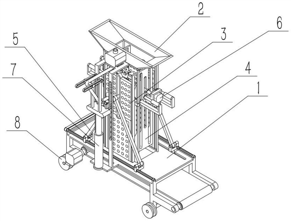
[0032] like Figure 1-10 As shown, a mining coal crusher includes a base structure 1, a feed seat 2, a side baffle 3, a main baffle 4, a linkage mechanism 5, a coal crushing mechanism 6, a dust reduction mechanism 7 and a wheel mechanism 8. The feeding seat 2 is connected to the upper end of the base structure 1, and two side baffles 3 are provided. The two side baffles 3 are respectively connected to the front and rear ends of the middle part of the base structure 1, and the left and right ends of the middle part of the base structure 1 are respectively mirrored and symmetrically connected. A main baffle plate 4, the linkage mechanism 5 is connected to the middle part of the base structure 1, the left and right ends of the linkage mechanism 5 are respectively mirrored and symmetrically connected to a coal crushing mechanism 6, the dust suppression mechanism 7 is connected to the rear end of the base structure 1, and the wheel mechanism 8 is provided with Two, two wheel mechan...

specific Embodiment approach 2

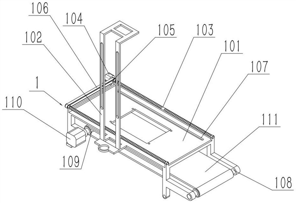
[0034] like Figure 1-10As shown, a mining coal crusher, the base structure 1 includes a base 101, a limit plate 102, a screw 103, a first motor 104, a first pulley 105, a first belt 106, and a limit bar hole 107 , the rotating rod 108, the second pulley 109, the second motor 110 and the second belt 111, the limit plate 102 is fixedly connected to the rear end of the base 101, and the front and rear ends of the base 101 are respectively rotated and connected to a lead screw 103, the first The output shaft of the motor 104 is fixedly connected to the leading screw 103 at the front end through a coupling, and the left end of each leading screw 103 is fixedly connected to a first pulley 105 respectively, and the two first pulleys 105 are connected through a first belt 106 transmission, The first motor 104 is fixedly connected to the left end of the base 101, and the front and rear sides of the base 101 are respectively provided with a limit bar hole 107, and the left and right en...

specific Embodiment approach 3

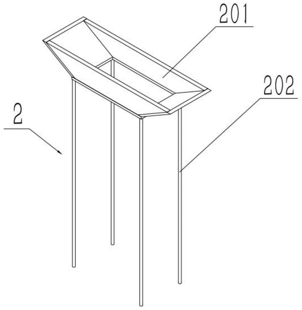
[0036] like Figure 1-10 As shown, a mine coal crusher, the feeding seat 2 includes a feeding chute 201 and a sliding rod 202, the four corners of the bottom end of the feeding chute 201 are fixedly connected to a sliding rod 202, and the lower ends of the four sliding rods 202 are It is fixed in the middle of the base 101. In the coal mine, the coal lumps of the coal mine are fed into the chute 201 to facilitate subsequent coal crushing treatment.


PUM


Abstract

The invention relates to a coal crusher, in particular to a mining coal crusher. The mining coal crusher comprises a base structure, a feeding base, two side baffles, main baffles, a linkage mechanism, coal crushing mechanisms, a dust falling mechanism and wheel mechanisms, wherein the feeding base is connected to the upper end of the base structure; the two side baffles are connected to the frontend and the rear end of the middle of the base structure respectively; the left end and the right end of the middle of the base structure are connected to the main baffles in a mirror symmetry mode respectively; the linkage mechanism is connected to the middle of the base structure; the left end and the right end of the linkage mechanism are connected to the coal crushing mechanisms in a mirror symmetry mode respectively; the dust falling mechanism is connected to the rear end of the base structure; and the two wheel mechanisms are rotationally connected to the left end and the right end of the lower end of the base structure respectively. The coal crushing mechanisms at the two ends conduct coal crushing treatment on composite coal briquettes which enter the feeding base and have coal briquettes on the outer surfaces and rocks in the inner parts through relative rotation.

Description

technical field [0001] The invention relates to a coal crusher, in particular to a mine coal crusher. Background technique [0002] For example, Publication No. CN201821939373.5 A Coal Crusher Dust Suppression Device This utility model discloses a coal crusher dust suppression device, which relates to the technical field of dust suppression devices, specifically a coal crusher dust suppression device, including , The interior of the coal crusher is provided with a storage tank, the inner wall of the storage tank is fixedly connected with a fixed column, the outer surface of the fixed column is sleeved with a pulverizer, and the inner wall of the storage tank is fixedly connected with a slideway. The coal crusher dust suppression device is set through the cooperation between the processing box, the placement tank, the bionano film, the discharge port and the canvas. When the crushed coal is discharged from the discharge port, due to the setting of the processing box and the c...

Claims


Application Information

Patent Timeline
IPC IPC(8): B02C7/06B02C7/11B02C7/16B60B33/00B01D47/06B02C23/00
CPCB01D47/06B02C7/06B02C7/11B02C7/16B02C23/00B60B33/0002
Inventor 曹丹
Owner 曹丹
Why Eureka
Try Eureka