Electromechanical integrated machining device

A processing device, electromechanical technology, applied in the direction of shearing device, metal processing equipment, accessories of shearing machine, etc., can solve the problems of staying beside the machine all the time, the operator's health is dangerous, and the operation is troublesome.

Active Publication Date: 2021-02-09
CHONGQING VOCATIONAL COLLEGE OF TRANSPORTATION
View PDF5 Cites 8 Cited by
  • Summary
  • Abstract
  • Description
  • Claims
  • Application Information

AI Technical Summary

Problems solved by technology

Among them, when the cutting device cuts materials such as plates and pipes, it is necessary to manually push the materials to move in the direction close to the cutter, so that the cutter can cut the longer materials into sections, which is the current cutting process. The method is still to cut b...

Method used


Image

  • Electromechanical integrated machining device
  • Electromechanical integrated machining device
  • Electromechanical integrated machining device

Examples


Embodiment 1

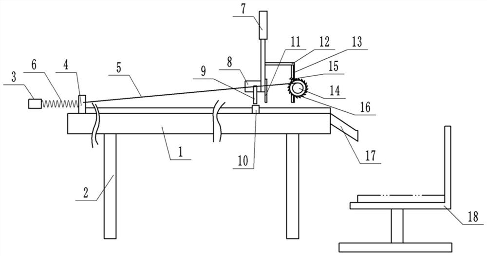
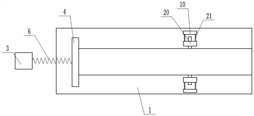
[0027] Basic as attached Figure 1-Figure 5 Shown: a mechanical and electrical integration processing device, including a frame (not shown in the figure), a cutting table 1 and a cutting tool 11, the cutting table 1 is a rectangular parallelepiped structure placed horizontally, and the bottom of the cutting table 1 is welded with a support rod 2. The right end of the cutting table 1 is the discharge end, and the top of the cutting table 1 is provided with a cylinder 7 for driving the cutting tool 11 to reciprocate vertically. The cylinder 7 is fixedly connected to the frame by bolts, and the cylinder rod of the cylinder 7 is fixed by screws. There is a cutting motor 8 for driving the cutting tool 11 to run. The table top of the cutting table 1 is horizontally slidably connected with a push plate 4. The specific sliding connection method can be as follows: the cutting table 1 is provided with a horizontal chute, the bottom of the push plate 4 is provided with a slider, and the...

Embodiment 2

[0035] combine Figure 6 As shown, a first hydraulic cylinder 22 is provided below the collector 18, and a first piston 23 is slidably connected to the inside of the first hydraulic cylinder 22, and a first piston is connected between the first piston 23 and the collector 18 by screws. Rod; the cutting table 1 is fixed with the second hydraulic cylinder 25 arranged horizontally by screws, the opening of the second hydraulic cylinder 25 is located at the right end, and the inside of the second hydraulic cylinder 25 is slidingly connected with the second piston 26, the second The piston 26 is fixedly connected with the second piston rod 28 arranged horizontally by screws, the right end of the second piston rod 28 and the push plate 4 are connected with a bent connecting rod 27, the second hydraulic cylinder 25 and the first hydraulic cylinder An oil pipe 24 is communicated between the cylinders 22 .

[0036] Thus, initially, the bottom of the collector 18 is slightly lower than...


PUM


Abstract

The invention relates to the field of electromechanical machining, in particular to an electromechanical integrated machining device. The electromechanical integrated machining device comprises a frame, a cutting table and a cutting tool, and an air cylinder used for driving the cutting tool to vertically move back and forth is arranged on the outer side of the cutting table; a push plate is transversely connected to the table top of the cutting table in a sliding mode; one end of the cutting table is a discharging end; a rope roller is arranged on the outer side of the discharging end of thecutting table; a ratchet wheel is coaxially and fixedly connected to the rope roller; a pawl abutting against teeth of the ratchet wheel is hinged to the frame; a rotating shaft is coaxially and fixedly connected to the ratchet wheel and rotatably connected to the frame; a toothed gear is arranged on the rotating shaft in a sleeved mode; a one-way bearing is arranged between the toothed gear and the rotating shaft; a rack meshed with the toothed gear is fixedly connected to an air cylinder rod of the air cylinder and is vertically arranged; and a pull rope is wound around the rope roller, andthe end, away from the rope roller, of the pull rope is fixedly connected to the push plate. By means of the scheme, automatic feeding and cutting of materials are achieved.

Description

technical field [0001] The invention relates to the field of electromechanical processing, in particular to an electromechanical integrated processing device. Background technique [0002] Mechatronics technology is a general term for the combination of mechanical technology and electronic technology. The current processing devices are usually mechatronic processing devices, such as mechatronic drilling machines, grinding machines, cutting devices and cleaning devices. Among them, when the cutting device cuts materials such as plates and pipes, it is necessary to manually push the materials to move in the direction close to the cutter, so that the cutter can cut the longer materials into sections, which is the current cutting process. The method is still to cut by manual feeding, so that the operator needs to stay beside the machine all the time, and the operation is more troublesome; because it is manual feeding, if the operator does not pay attention, the hand of the opera...

Claims


Application Information

Patent Timeline
IPC IPC(8): B23D15/08B23D15/14B23D33/00B23D33/02
CPCB23D15/08B23D15/14B23D33/00B23D33/02Y02P70/10
Inventor 熊如意王宏卢江林
Owner CHONGQING VOCATIONAL COLLEGE OF TRANSPORTATION
Why Eureka
Try Eureka