Mechanical lifting type engineering machinery transfer device
What is Al technical title?
Al technical title is built by PatSnap Al team. It summarizes the technical point description of the patent document.
A technology for construction machinery and transfer devices, which is applied in portable lifting devices, hoisting devices, transportation and packaging, etc. It can solve the problems of inability to protect the bottom of mechanical equipment, inability to lock wire ropes, and device collisions, etc., so as to improve the fixing effect Effect
Inactive Publication Date: 2021-02-09
姜泽圳
View PDF0 Cites 0 Cited by
Summary
Abstract
Description
Claims
Application Information
AI Technical Summary
This helps you quickly interpret patents by identifying the three key elements:
Problems solved by technology
Method used
Benefits of technology
Problems solved by technology
[0005] In order to solve the above technical problems, the present invention provides a mechanical lifting construction machinery transfer device to solve the problem that the existing mechanical lifting construction machinery transfer device cannot protect the bottom of the mechanical equipment, and cannot lock the wire rope and mechanically The problem that the device is easy to shake and collide with the device when moving
Method used
Image
Click on the blue label to locate the original text in one second.
Reading with bidirectional positioning of images and text.
Examples
Embodiment
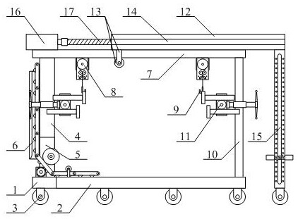
[0035] as attached figure 1 And attached figure 2As shown, a mechanical lifting type construction machinery transfer device includes a bottom plate 1, a through groove 2, a moving wheel 3, a vertical plate 4, a mounting groove 5, an equipment bracket structure 6, a top plate 7, and a locking lifting frame structure 8 , hook 9, support column 10, equipment fixing frame mechanism 11, extension beam 12, pulley frame 13, threaded hole 14, extension bracket structure 15, rotating motor 16 and lead screw 17, and the opening of the said through slot 2 is opened on the right The inner right side of the base plate 1; the moving wheels 3 are respectively arranged at the front and rear ends of the lower part of the base plate 1 and the lower part of the extension bracket structure 15; the vertical plate 4 is welded on the left side of the upper part of the base plate 1; the installation The slot 5 is set on the inner lower part of the riser 4; the equipment bracket structure 6 is insta...
PUM
Abstract
The invention provides a mechanical lifting type engineering machinery transfer device which comprises a bottom plate, a through groove, moving wheels, a vertical plate, a mounting groove, an equipment bracket structure, a top plate, locking crane boom structures, hooks, supporting columns, equipment fixing frame mechanisms, an extending cross beam, pulley brackets, threaded holes, extending support structures, a rotating motor and a lead screw, wherein the through groove opens rightwards and is formed in the right side of the interior of the bottom plate; and the moving wheels are arranged atthe front end and the rear end of the lower portion of the bottom plate and the lower portion of the extending support structures respectively. The mechanical lifting type engineering machinery transfer device has the beneficial effects that through the arrangement of an equipment supporting plate, reinforcing cross beams, a servo motor and a rolling wheel, the servo motor drives the rolling wheel to rotate, the rolling wheel rubs with the lower portion of the equipment supporting plate to push the equipment supporting plate to transversely move towards the right side, the bottom of mechanical equipment can be supported easily, and the bottom of the mechanical equipment is prevented from being collided during transportation, so that the bottom of the mechanical equipment is protected.
Description
technical field [0001] The invention belongs to the technical field of mechanical equipment, and in particular relates to a mechanical lifting type construction machinery transfer device. Background technique [0002] With the maturity of my country's machinery and equipment technology, various machinery and equipment are developing rapidly. In some occasions, the equipment needs to be transported from one location to another. Because manual transportation is difficult, it is necessary to use a transportation mechanical device for transportation. Generally, large equipment such as forklifts, cranes or cranes are used to move the position. [0003] However, the existing mechanical lifting construction machinery transfer device still has the problems that the bottom of the mechanical equipment cannot be protected, the steel wire rope cannot be locked, and the mechanical equipment is easy to shake and collide with the device when moving. [0004] Therefore, it is very necessary...
Claims
Application Information
Patent Timeline
Application Date:The date an application was filed.
Publication Date:The date a patent or application was officially published.
First Publication Date:The earliest publication date of a patent with the same application number.
Issue Date:Publication date of the patent grant document.
PCT Entry Date:The Entry date of PCT National Phase.
Estimated Expiry Date:The statutory expiry date of a patent right according to the Patent Law, and it is the longest term of protection that the patent right can achieve without the termination of the patent right due to other reasons(Term extension factor has been taken into account ).
Invalid Date:Actual expiry date is based on effective date or publication date of legal transaction data of invalid patent.