Precise lifting method for plant equipment foundation

A kind of equipment-based and sophisticated technology, which is applied in basic structure engineering, basic structure repair, construction, etc., can solve problems such as failure to meet the design foundation bearing capacity requirements, settlement and deformation of backfill soil layers, and incompact backfill soil layers. Controllability and accuracy, strengthening the bearing capacity of the foundation, reducing the effect of disturbance

Active Publication Date: 2021-02-09
BEIJING HENGXIANG HONGYE FOUND REINFORCEMENT TECH CO LTD
View PDF7 Cites 3 Cited by
  • Summary
  • Abstract
  • Description
  • Claims
  • Application Information

AI Technical Summary

Problems solved by technology

In a precision equipment factory building, there is no equipment foundation in the factory building. The equipment is placed directly on the 200mm thick concrete floor, and the backfill soil layer is 1-9m below the ground. Because there are gaps between the concrete floor and the backfill soil layer and the backfill soil layer is not dense. The bearing capacity requirements of the designed foundation are not met, resulting in the settlement and deformation of the backfill soil layer
Due to the deformation of the foundation at the bottom of the equipment, the processing accuracy of the equipment is out of tolerance. Therefore, how to precisely level the equipment and reinforce the backfill soil layer without affecting the operation of the equipment is the problem we are facing now.

Method used


Image

  • Precise lifting method for plant equipment foundation
  • Precise lifting method for plant equipment foundation
  • Precise lifting method for plant equipment foundation

Examples


Embodiment Construction

[0038] The present invention will be described in further detail below in conjunction with the accompanying drawings.

[0039] The invention discloses a method for precisely raising the foundation of plant equipment, which is described below by taking strip-shaped equipment as an example. Include the following steps:

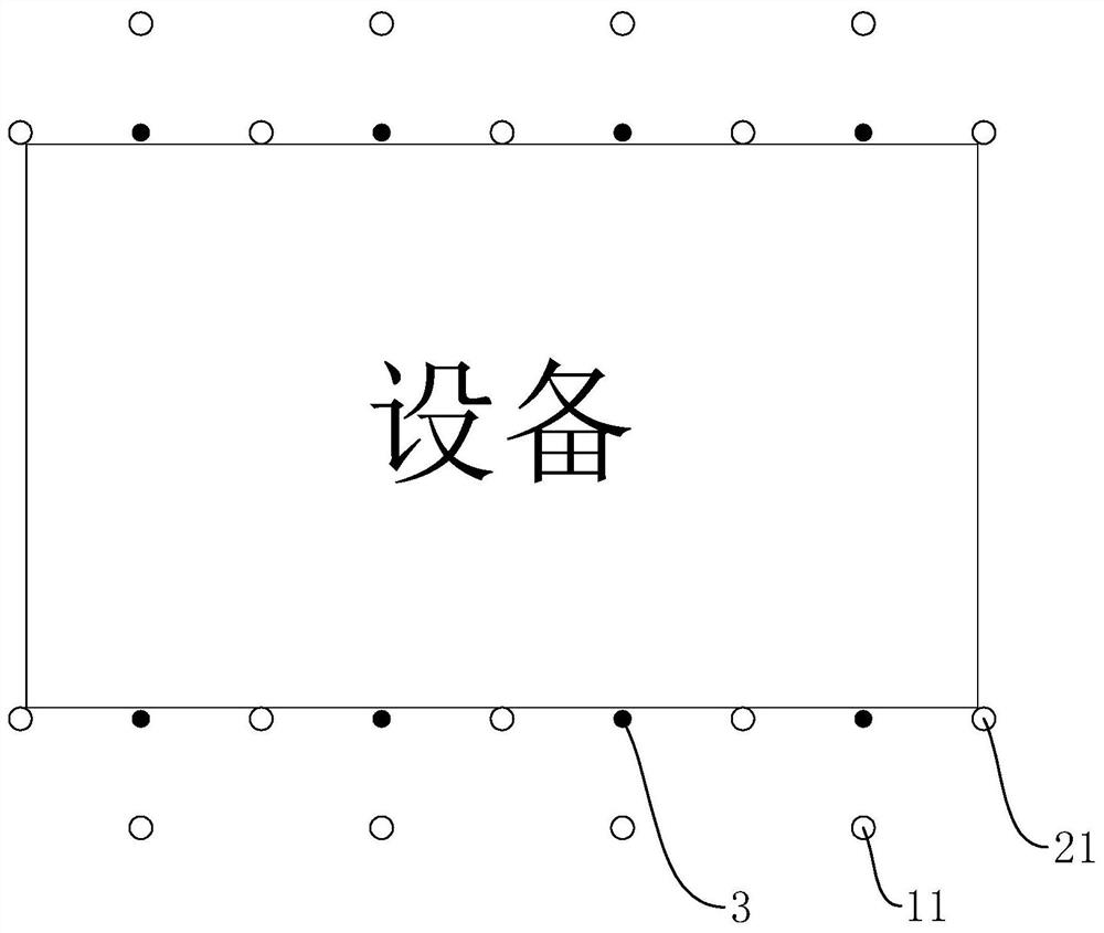
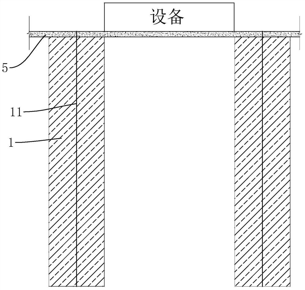
[0040] S1, forming curtain wall 1: refer to figure 1 and figure 2 Drill and inject curtain holes 11 vertically on both sides of the lifting section of the equipment. The diameter of the curtain holes 11 is 42 mm. A plurality of curtain holes 11 are evenly spaced along the length direction of the equipment. Between adjacent curtain holes 11 The spacing is 2-3m, and the curtain hole 11 is 1-2m away from the equipment. Grout is injected into the curtain hole 11. The grouting range overlaps with each other to form two parallel curtain walls 1. The height of the curtain wall 1 can be the backfill soil layer thickness of. The curtain wall 1 separates the equipmen...


PUM


Abstract

The invention relates to a precise lifting method for a plant equipment foundation. The precise lifting method comprises the following steps that S1, curtain walls are formed, specifically, holes arevertically and downwards drilled in two sides, needing to be lifted, of the equipment to form curtain holes, and the curtain holes are grouted to form two curtain walls which are parallel to each other; S2, a reinforcing body is formed, specifically, obliquely-downward grouting holes are formed in the outer contour lines of the equipment in the length direction of the curtain walls, grouting is conducted in the grouting holes, grouting is conducted between the two curtain walls at the bottom of the equipment foundation bottom plate to form the reinforcing body attached to the lower surface ofthe bottom plate, and the reinforcing body and the two curtain walls are combined to form an n-shaped structure; and S3, lifting is conducted, specifically, the grouting hole serves as the lifting hole, a hole is obliquely drilled downwards until the hole is drilled to the position below the reinforcing body and located between the two curtain walls, pressure grouting is conducted on the bottom ofthe lifting hole to fill and reinforce the surrounding backfill layer, pressure grouting continues, retreating type grouting is adopted, and the equipment is lifted to the set lifting height. The precise lifting method has the advantages of being small in surrounding disturbance, controllable in lifting height and high in lifting precision.

Description

technical field [0001] The invention relates to the technical field of building uplift, in particular to a method for precise uplifting of plant equipment foundations. Background technique [0002] At present, the construction of factory buildings is generally a frame structure, and the foundation is an independent foundation, which mainly relies on columns and independent foundations for load bearing. In a precision equipment factory building, there is no equipment foundation in the factory building. The equipment is placed directly on the 200mm thick concrete floor, and the backfill soil layer is 1-9m below the ground. Because there are gaps between the concrete floor and the backfill soil layer and the backfill soil layer is not dense. The bearing capacity requirements of the designed foundation were not met, resulting in the settlement and deformation of the backfill soil layer. Due to the deformation of the foundation at the bottom of the equipment, the processing accu...

Claims


Application Information

Patent Timeline
Patent Type & Authority Applications(China)
IPC IPC(8): E02D27/44E02D35/00E02D3/12E02D19/18
CPCE02D27/44E02D35/005E02D3/12E02D19/18E02D35/00E02D37/00
Inventor 崔学栋吴继光崔腾跃
Owner BEIJING HENGXIANG HONGYE FOUND REINFORCEMENT TECH CO LTD
Why Eureka
Try Eureka