
Infrared fingerprint identification module and electronic device

A fingerprint identification module and electronic device technology, which is applied in character and pattern recognition, fingerprint/palmprint acquisition/organization, print image collection, etc., which can solve the problems of large internal space occupation of electronic devices and small fingerprint identification.

Inactive Publication Date: 2021-02-09
NANCHANG OUFEI BIOLOGICAL IDENTIFICATION TECH
View PDF0 Cites 0 Cited by
  • Summary
  • Abstract
  • Description
  • Claims
  • Application Information

AI Technical Summary

Problems solved by technology

In this way, the internal space of the electronic device is relatively large, and the light emitting angle of the point light source of the infrared light emitting device 10a is small, resulting in a small area for fingerprint identification, and the position of the infrared fingerprint identification module 100a is relatively fixed.

Method used


Image

  • Infrared fingerprint identification module and electronic device
  • Infrared fingerprint identification module and electronic device
  • Infrared fingerprint identification module and electronic device

Examples


Embodiment Construction

[0022] The following will clearly and completely describe the technical solutions in the embodiments of the present application with reference to the accompanying drawings in the embodiments of the present application. Obviously, the described embodiments are only part of the embodiments of the present application, not all of them. Based on the embodiments in this application, all other embodiments obtained by persons of ordinary skill in the art without making creative efforts belong to the scope of protection of this application.

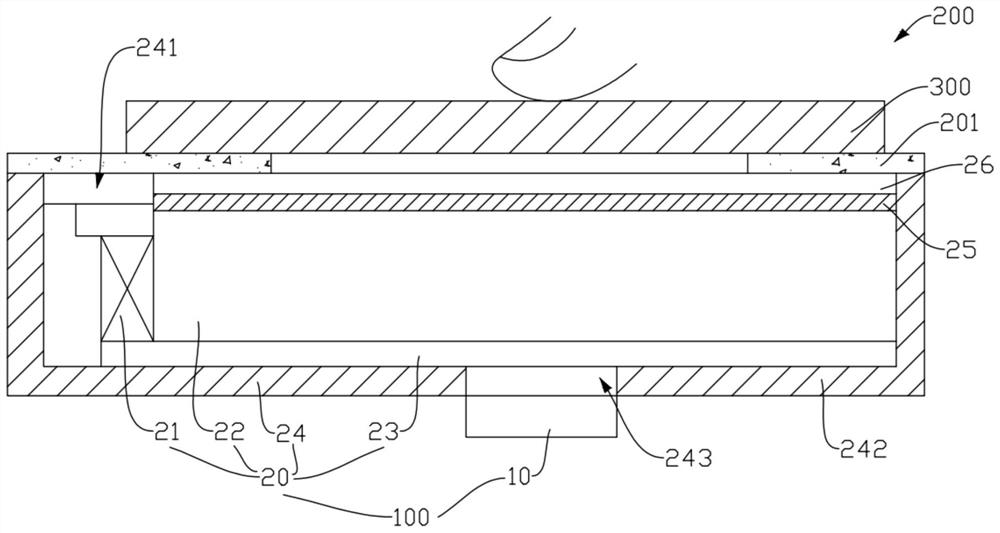
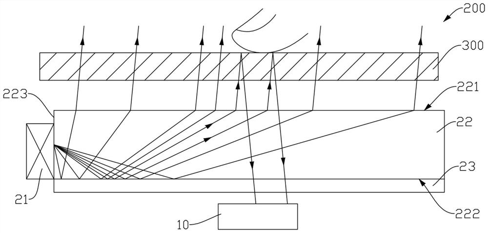
[0023] Please see figure 2 The electronic device 100 of the present application shown is disposed below the liquid crystal panel 300 of the electronic device 200 . It can be understood that the lower here refers to the back side of the light emitting surface 301 of the liquid crystal panel 300 . The infrared fingerprint recognition module 100 includes an infrared receiving component 10 and a backlight component 20 . The backlight assembly 20 in...


PUM


Abstract

The invention relates to an infrared fingerprint identification module which is arranged below a liquid crystal panel of an electronic device. The liquid crystal display panel comprises an infrared receiving assembly and a backlight assembly. The backlight assembly comprises a light source, a light guide plate and a reflector; the light guide plate is located between the infrared receiving assembly and the liquid crystal display panel, and the reflector is located between the light guide plate and the infrared receiving assembly. The light source is fixed to the position, close to the side edge, of the light guide plate and used for emitting infrared light to the light guide plate towards the side edge, and the infrared light is emitted into the liquid crystal panel from the side, away from the reflector, of the light guide plate under the action of the reflector. When a finger of a user touches the liquid crystal panel, the infrared receiving assembly is used for receiving infrared light reflected back by the finger so as to achieve a fingerprint recognition function. According to the infrared fingerprint identification module, a light emitting device usually arranged below the liquid crystal panel is omitted, the internal space of the electronic device is saved, and the fingerprint identification area is increased.

Description

technical field [0001] The present application relates to the field of electronic devices, in particular to a compact infrared fingerprint recognition module and an electronic device using the infrared fingerprint recognition module. Background technique [0002] Currently, electronic devices are usually provided with a fingerprint recognition function, especially under the trend of full screens, under-screen fingerprint recognition technology has been paid more and more attention. At present, the infrared light emitting device 10a in the infrared light fingerprint module 100a is placed under the backlight assembly 200a as an independent device (see figure 1 ), and the infrared light emitting device 10a and the infrared light receiving device 20a are arranged side by side. This occupies a large internal space of the electronic device, and the point light source angle of the infrared light emitting device 10a is small, resulting in a small area for fingerprint identification...

Claims


Application Information

Patent Timeline
IPC IPC(8): G06K9/00
CPCG06V40/1318
Inventor 安宏鹏马铁球钟东方杨飞熊鹏
Owner NANCHANG OUFEI BIOLOGICAL IDENTIFICATION TECH
Learn More