Wall-mounted drawing type combined LED display screen
An LED display screen and pull-out technology, applied in the directions of instruments, identification devices, supporting machines, etc., can solve the problems of inconvenient maintenance, difficult installation, low maintenance and maintenance efficiency, etc., and achieve simple installation and combination. The effect of convenient and convenient maintenance and repair operation
- Summary
- Abstract
- Description
- Claims
- Application Information
AI Technical Summary
Problems solved by technology
Method used
Image
Examples
Embodiment 1
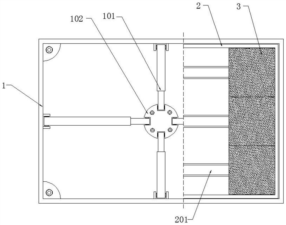
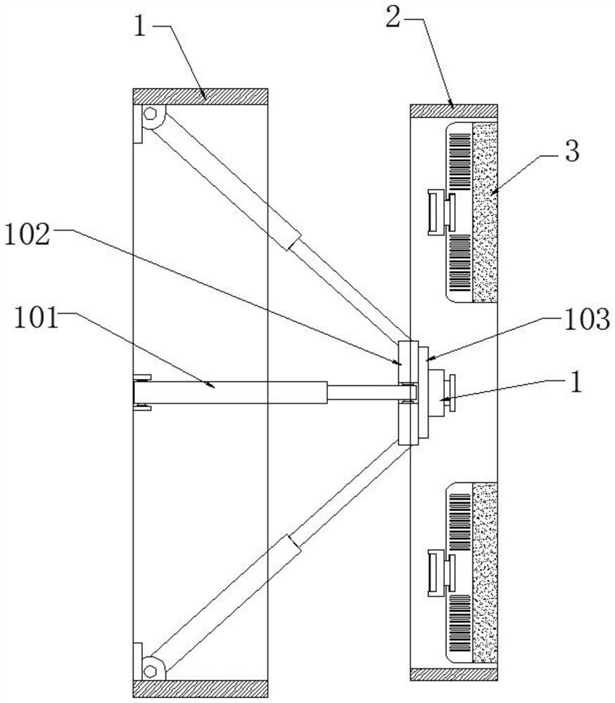
[0028] refer to figure 1 , 2 And 5-7, a wall-mounted pull-type combined LED display, including an installation frame 1, a movable inner frame 2 and an LED display assembly 3, the installation frame 1 is fixed on the wall by bolts, and the side wall of the installation frame 1 There are threading holes, and the installation frame 1 is equipped with a drawing assembly, which is fixedly connected with the movable inner frame 2, and the movable inner frame 2 is drawn in the installation frame 1 through the drawing assembly, and the installation frame 1 and the movable inner frame 2 is provided with a locking mechanism, the locking mechanism is a card slot and a card block, hidden pull handles are installed on the two side walls of the movable inner frame 2, and a longitudinal installation notch 202 is opened on the side wall of the movable inner frame 2 , the movable inner frame 2 is fixedly provided with mounting beams 201 equidistant from top to bottom, and multiple sets of LED...
Embodiment 2
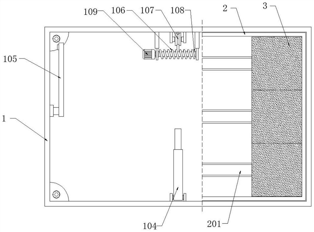
[0036] refer to Figure 3-7 The difference between this embodiment and Embodiment 1 is that the specific structural design of the drawing assembly in this embodiment is different. In this embodiment, the drawing assembly includes a stable telescopic rod 104, a rotating arm 105, a traction cable 106, Fixed pulley 107, winding rod 108 and motor 109, wherein, rotating support arm 105 is provided with two, and the upper end of two rotating support arms 105 is respectively rotated and installed in the middle part of installation frame 1 both sides inner wall, two rotating support arms 105 The upper ends of the movable inner frame 2 are respectively rotatably connected to the inner walls on both sides of the movable inner frame 2, and the middle position of the bottom of the movable inner frame 2 is rotatably connected to one end of the stable telescopic rod 104, and the other end of the stable telescopic rod 104 is rotatably connected to the middle part of the movable inner frame 2 ...
PUM
 Abstract
Description
Claims
Application Information
 - R&D
- Intellectual Property
- Life Sciences
- Materials
- Tech Scout
- Unparalleled Data Quality
- Higher Quality Content
- 60% Fewer Hallucinations
Browse by: Latest US Patents, China's latest patents, Technical Efficacy Thesaurus, Application Domain, Technology Topic, Popular Technical Reports.
© 2025 PatSnap. All rights reserved.Legal|Privacy policy|Modern Slavery Act Transparency Statement|Sitemap|About US| Contact US: help@patsnap.com


