Automatic numerical control lathe

A CNC lathe and automatic technology, applied in the field of CNC lathes, can solve the problems of insufficient cleaning of debris, inconvenient collection of metal scraps, and insufficient comprehensiveness.

Pending Publication Date: 2021-02-12
闫玉乐
View PDF1 Cites 3 Cited by
  • Summary
  • Abstract
  • Description
  • Claims
  • Application Information

AI Technical Summary

Problems solved by technology

[0006] In order to solve the technical problems existing in the background technology, the present invention proposes an automatic numerical control lathe, which solves the problem that the scraps after processing are not cleaned carefully enough, not comprehensive enough, and it is inconvenient to collect small metal scraps

Method used


Image

  • Automatic numerical control lathe
  • Automatic numerical control lathe
  • Automatic numerical control lathe

Examples


Embodiment 1

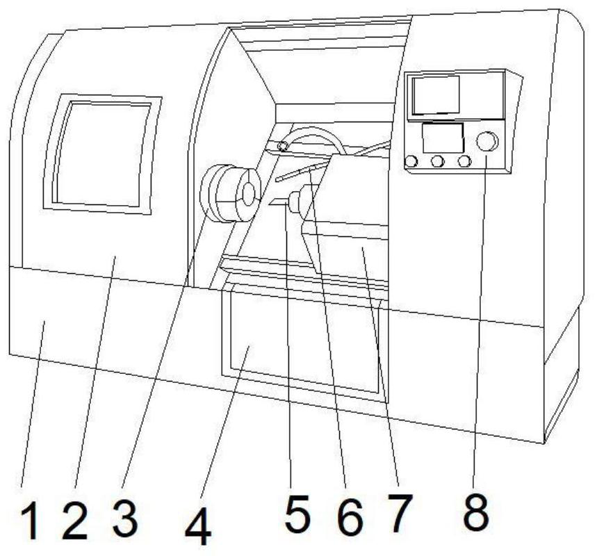
[0035] Such as Figure 1-2 , a technical solution proposed by the present invention: an automatic numerically controlled lathe, comprising a main body 1, a protective door 2 is fixedly connected to the left side of the front top of the main body 1, and a feeding device 3 is provided at the middle position on the left side of the inner cavity of the main body 1, and the feeding device 3 is The left end of the device 3 runs through the main body 1, and the middle position on the right side of the inner cavity of the main body 1 is provided with a moving mechanism 7. The middle position on the left side of the moving mechanism 7 is fixedly connected with a cutter 5, and the top right side of the moving mechanism 7 is fixedly connected with a cooling pipe 6. A collection device 4 is provided at the middle of the bottom of the inner cavity of the main body 1, and a controller 8 is fixedly connected to the top right side of the front of the main body 1.

[0036]Wherein, feeding devi...

Embodiment 2

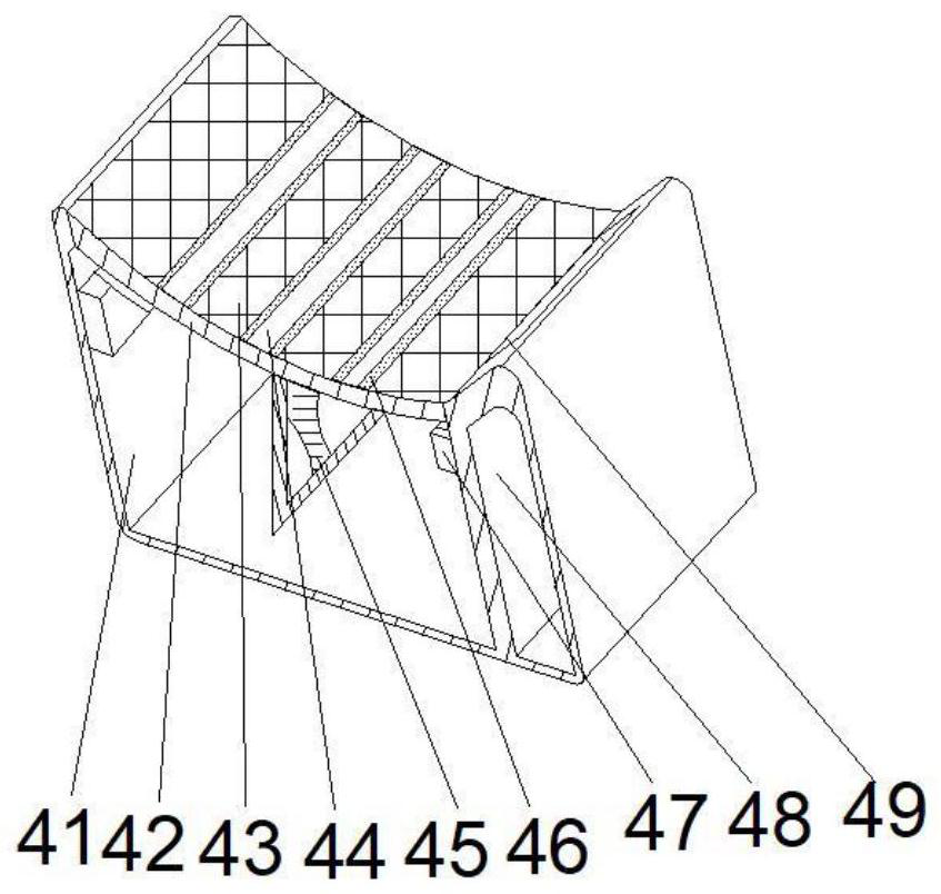
[0039] Such as Figure 1-3 As shown, on the basis of Embodiment 1, the present invention provides a technical solution: the collection device 4 includes a box body 41, the top of the box body 41 is provided with an arc-shaped top plate 42, and the top of the arc-shaped top plate 42 is provided with a circulation surface 43 , the arc top plate 42 is fixedly connected with a baffle 44, the two sides of the baffle 44 are fixedly connected with a magnet 46, the top of the inner wall on both sides of the box body 41 is fixedly connected with a connecting block 47, and the middle position of the inner cavity bottom of the box body 41 is fixed A partition 45 is connected, a waste bin 48 is arranged on the right side of the box body 41 , and a collection port 49 is opened on the top of the waste bin 48 .

[0040] When in use, clamp the workpiece, press the open key on the controller 8, input the program, close the protective door, the moving mechanism 7 works, the moving mechanism 7 d...

Embodiment 3

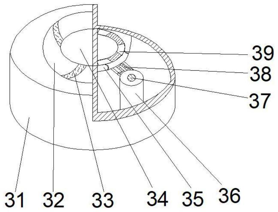
[0042] Such as Figure 1-6 As shown, on the basis of Embodiment 1 and Embodiment 2, the present invention provides a technical solution: the bottom of the arc-shaped block 33 is fixedly connected with an elastic ball 334, and the top of the arc-shaped block 334 is fixedly connected with a connecting plate 331. A swing plate 332 is provided at the bottom of the plate 331 , and a booster plate 333 is fixedly connected to the right side of the bottom of the swing plate 332 .

[0043] Wherein, the top of the arc-shaped baffle is provided with a circulation groove 421, and the bottom of the inner cavity of the circulation groove 421 is fixedly connected with an adjusting plate 422, and the top right side of the arc-shaped top plate 42 is provided with a groove 425, and the bottom right side of the arc-shaped top plate 42 A top post 424 is fixedly connected, and the right side of the arc-shaped top plate 42 is located on both sides of the top post 424 to open through holes 423 .

...


PUM


Abstract

The invention discloses an automatic numerical control lathe. The automatic numerical control lathe comprises a body, a protective door is fixedly connected to the left side of the top of the front face of the body, a feeding device is arranged at the middle position of the left side of an inner cavity of the body, the left end of the feeding device penetrates through the body, and a moving mechanism is arranged at the middle position of the right side of the inner cavity of the body. A cutter is fixedly connected to the middle position of the left side of the moving mechanism, a cooling pipeis fixedly connected to the top of the right side of the moving mechanism, a collecting device is arranged at the middle position of the bottom of the inner cavity of the body, and a controller is fixedly connected to the top of the right side of the front face of the body. The invention relates to the technical field. According to the automatic numerical control lathe, scraps generated during machining fall onto the collecting device, rapid collection is achieved, scraps generated after machining are cleaned away comprehensively and finely, small metal scraps can be collected conveniently, inthe feeding process, the feeding device shrinks slightly after making contact with a workpiece, the contact strength is increased, and the workpiece is fixed and clamped.

Description

technical field [0001] The invention relates to the technical field of numerically controlled lathes, in particular to an automatic numerically controlled lathe. Background technique [0002] CNC lathes are mainly used for cutting the inner and outer cylindrical surfaces of shaft parts or disc parts, the inner and outer conical surfaces of any cone angle, the complex rotary inner and outer curved surfaces, cylinders, and conical threads, etc., and can perform grooving, drilling, reaming, Reaming and boring etc. The CNC machine tool automatically processes the processed parts according to the pre-programmed processing program. We write the processing route, process parameters, tool trajectory, displacement, cutting parameters and auxiliary functions of the parts into a processing program sheet according to the instruction code and program format specified by the CNC machine tool, and then record the contents of the program sheet On the control medium, it is then input into ...

Claims


Application Information

Patent Timeline
Patent Type & Authority Applications(China)
IPC IPC(8): B23B7/14B23B15/00B23Q11/08B23Q11/00
CPCB23B7/12B23Q7/00B23Q11/0046B23Q11/08
Inventor 闫玉乐
Owner 闫玉乐
Why Eureka
Try Eureka