Iron metal pipe positioning and cutting device and working method thereof

A technology for positioning cutting and metal pipes, which is applied in the direction of shearing devices, metal processing equipment, and attachments of shearing machines, etc. It can solve problems such as deviations in artificial drawing lines, cutting deviations, and easy accidental injuries to staff, etc., to achieve convenient removal and Storage, convenient and stable adjustment, increase the effect of clamping stability

Inactive Publication Date: 2021-02-12
阜南县中泰工艺品有限公司
View PDF0 Cites 0 Cited by
  • Summary
  • Abstract
  • Description
  • Claims
  • Application Information

AI Technical Summary

Problems solved by technology

[0003] When cutting ferrous metal pipes, it is often necessary to manually draw lines and cut them. There are deviations in artificial drawing lines, resulting in errors and defects in the dimensions of ferrous metal pipes after cutting; and when ferrous metal pipes are cut, they are usually held manually. The splash of debris generated by cutting is easy to accidentally injure the staff, and the manual cutting is not stable enough, resulting in deviation in cutting; the current iron metal pipe cutting equipment is inconvenient to adjust, so we propose a positioning cutting device for iron metal pipe and how it works

Method used


Image

  • Iron metal pipe positioning and cutting device and working method thereof
  • Iron metal pipe positioning and cutting device and working method thereof
  • Iron metal pipe positioning and cutting device and working method thereof

Examples


Embodiment 1

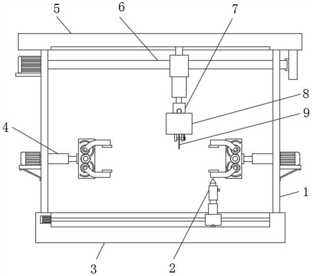
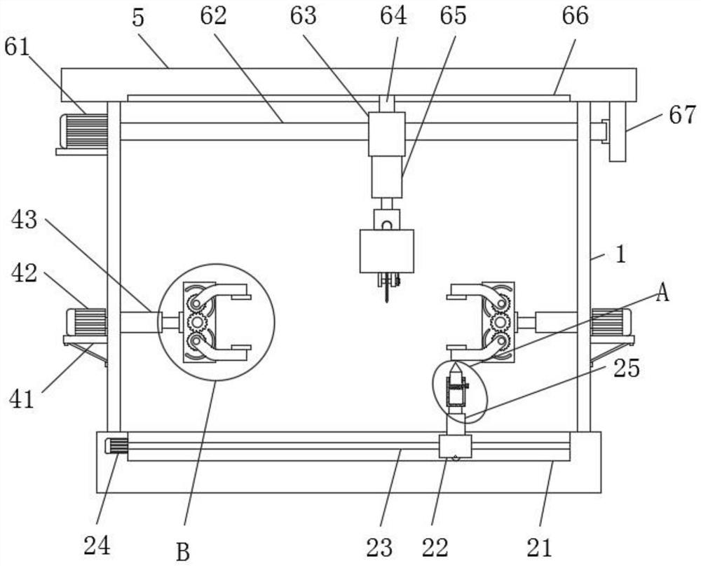
[0035] see Figure 1-6 As shown, a ferrous metal pipe positioning and cutting device includes a fixed rod 1, a positioning component 2, a bottom plate 3, a clamping component 4, a top plate 5, an adjustment component 6, a dust suction component 7, a cutting machine body 8 and a cutting piece 9 , the upper side of the bottom plate 3 is provided with a positioning assembly 2, the upper end of the bottom plate 3 is installed with four sets of fixed rods 1, the upper end of the four sets of fixed rods 1 is installed with a top plate 5, the lower end of the top plate 5 is provided with an adjustment assembly 6, and the upper side of the bottom plate 3 is provided with a clamping Component 4, the lower side of the top plate 5 is equipped with a cutting machine body 8, the lower side of the cutting machine body 8 is equipped with a cutting blade 9, and the inside of the cutting machine body 8 is provided with a dust suction component 7;

[0036] The positioning assembly 2 includes an...

Embodiment 2

[0046] A working method for positioning and cutting an iron metal pipe. The working method for positioning and cutting an iron metal pipe includes the following specific steps:

[0047] Step 1, when the iron metal pipe is positioned and cut, the second electric telescopic rod 43 is energized to drive the installation plate 44 and the clamp 45 to adjust to the appropriate distance, and then the staff places the two sections of the metal tube in the clamp 45 respectively, and fixes the plate The clamping motor 491 on the 492 is energized and works, and the clamping motor 491 drives the driving rod 49 to run, and the first driving gear 48 and the second driving gear 481 drive the driven gear 47 respectively, because the driven gear 47 is installed on the transmission rod 46 , the transmission rod 46 will also rotate, and the transmission rod 46 will drive the clamp 45 again. Because the tooth inclination angles of the first driving gear 48 and the second driving gear 481 are oppos...


PUM


Abstract

The invention discloses an iron metal pipe positioning and cutting device and a working method thereof. The iron metal pipe positioning and cutting device comprises a positioning motor, a first electric telescopic rod, a pen containing barrel, a line drawing pen, rotating motors, clamps, driven gears, second driving gears, clamping motors, a gear motor and a third electric telescopic rod. The positioning motor is assembled at the position, in a bottom plate, of one end of a first screw, the first electric telescopic rod is assembled at the upper end of an adjusting block, the pen containing barrel is installed at the upper end of the first electric telescopic rod, the line drawing pen is installed in a fixing ring in a meshed mode, the rotating motors are assembled at the upper ends of containing plates, the second driving gears are installed on driving rods, the driven gears are installed on transmission rods, and the clamps are installed at the positions, on the transmission rods, ofthe outer sides of the driven gears. According to the device, manual line drawing cutting is not needed, deviation caused by manual line drawing is avoided, meanwhile, manual holding is not needed inthe cutting process, and the situation that chippings generated by cutting splash to accidentally injure workers is avoided.

Description

technical field [0001] The invention belongs to the technical field of metal pipe processing, and relates to a positioning cutting device, in particular to a positioning cutting device for ferrous metal pipes and a working method thereof. Background technique [0002] A pipeline is a device used to transport gas, liquid or fluid with solid particles connected by pipes, pipe connectors and valves. Usually, after the fluid is pressurized by blowers, compressors, pumps and boilers, it flows from the high-pressure part of the pipeline to the low-pressure part, and it can also be transported by the pressure or gravity of the fluid itself. Pipes are widely used, mainly in water supply, drainage, heat supply, gas supply, long-distance transportation of oil and natural gas, agricultural irrigation, water conservancy projects and various industrial installations. The types of pipes include plastic pipes and metal pipes. [0003] When cutting ferrous metal pipes, it is often necessa...

Claims


Application Information

Patent Timeline
Patent Type & Authority Applications(China)
IPC IPC(8): B23D19/00B23D33/00B23D33/02B23D33/12B23Q11/00
CPCB23D19/00B23D33/00B23D33/02B23D33/12B23Q11/0046
Inventor 锁雷娜李茂
Owner 阜南县中泰工艺品有限公司
Why Eureka
Try Eureka