Machining method of wing-shaped missile shaft high-precision part

A processing method and high-precision technology, applied in the processing field of high-precision parts of airfoil elastic shaft, can solve problems such as deformation and distortion, inability to achieve real-time monitoring of the elastic wing, affecting the high-precision requirements of calibration instruments, etc. Effects of Balance Problems

Active Publication Date: 2021-02-12
XIAN NORTH ELECTRO OPTIC TECH DEFENSE
View PDF13 Cites 2 Cited by
  • Summary
  • Abstract
  • Description
  • Claims
  • Application Information

AI Technical Summary

Problems solved by technology

[0003] As the key reference part of the missile shaft detector, the precision of the bomb wing is much higher than that of ordinary parts. Because of its unique structure, it is affected by the force and deformation of the process system during processing, and it is necessary to monitor the processing of the parts in real time at any time. However, when measuring the size of the space, only three-coordinate measuring instruments can be used, and the real-time monitoring of the wings on the station cannot be achieved.
[0004] In addition, in order to more realistically simulate the structure of the missile, two sections of high-precision arc surfaces are designed on the incomplete sector. The line connecting the center point in space is the design basis. The processing difficulties are mainly manifested in high-precision welding forming and precision machining. In terms of in-situ detection, for example, the asymmetric wing structure is easily deformed and twisted under the action of cutting force, clamping force and other factors, which affects the high-precision requirements of the calibration instrument; Dynamic balance, precise positioning on the machine tool, and in-position detection become bottlenecks in processing

Method used


Image

  • Machining method of wing-shaped missile shaft high-precision part
  • Machining method of wing-shaped missile shaft high-precision part
  • Machining method of wing-shaped missile shaft high-precision part

Examples


no. 1 approach

[0076] This embodiment relates to a method for processing high-precision parts of an airfoil shaft, comprising the following steps:

[0077] Step 001. Selecting raw materials for processing target airfoil parts and blanking;

[0078] Step 002. Split the target airfoil part into welding pieces according to the part structure, and obtain the raw materials required for each welding piece;

[0079] Step 003. Machining each welded single piece;

[0080] Step 004. Assemble and weld the single pieces to form the wing assembly, and vibrate to relieve stress;

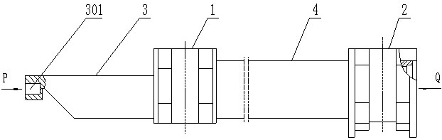
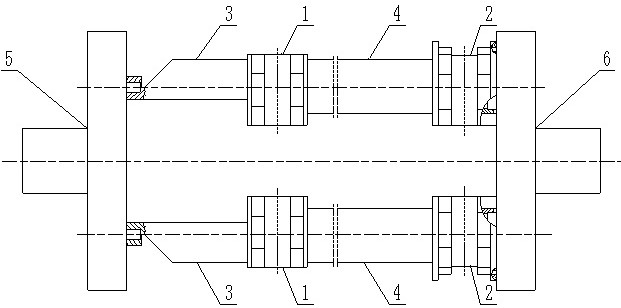
[0081] Step 005. Take two wing assemblies, and use an auxiliary processing device to clamp the two wing assemblies at the same time. The two wing assemblies and the auxiliary processing device form a rotary structure, and the rotary structure can rotate around the center of rotation;

[0082] Step 006. Continue to machine the structure of the revolving body, remove the auxiliary processing device until it becomes the target ai...

no. 2 approach

[0092] This embodiment relates to a method for processing high-precision parts of an airfoil shaft, comprising the following steps:

[0093] Step 001. Selecting raw materials for processing target airfoil parts and blanking;

[0094] Step 002. Split the target airfoil part into welding pieces according to the part structure, and obtain the raw materials required for each welding piece;

[0095] Step 003. Machining each welded single piece;

[0096] Step 004. Assemble and weld the single pieces to form the wing assembly, and vibrate to relieve stress;

[0097] Step 005. Take two wing assemblies, and use an auxiliary processing device to clamp the two wing assemblies at the same time. The two wing assemblies and the auxiliary processing device form a rotary structure, and the rotary structure can rotate around the center of rotation;

[0098] Step 006. Continue to machine the structure of the revolving body, remove the auxiliary processing device until it becomes the target ai...


PUM


Abstract

The invention provides a machining method of a wing-shaped missile shaft high-precision part. The machining method includes the following steps that a target wing-shaped part is split into welding single pieces according to the structure of the part; each welding single piece is machined; the single pieces are assembled and welded to form a missile wing assembly, and vibration is performed to relieve the stress; two missile wing assemblies are taken, an auxiliary machining device is used for clamping the two missile wing assemblies at the same time, and the two missile wing assemblies and theauxiliary machining device form a revolving body structure; and machining is performed continuously, and the auxiliary machining device is removed until a target wing-shaped part is formed. Accordingto the method, the space virtual point in the central position of the missile wing is changed into the actually-existing central axis by the aid of the auxiliary machining device, so that the arc of the missile wing forms a symmetrical and measurable circle, in-situ detection is completed, and the purpose of real-time monitoring is achieved; meanwhile, unification of the design benchmark, the process benchmark and the detection benchmark is realized, no positioning and detection errors are generated in processing and detection, symmetrical processing of the missile wing is realized, and the dynamic balance problem during machining in the grinding process is solved.

Description

technical field [0001] The invention belongs to the technical field of precision mechanics of metal parts, and in particular relates to a processing method for high-precision parts of an airfoil bomb shaft. Background technique [0002] The bomb axis tester is a necessary calibration instrument for a certain key product, and the bomb wing is the key reference part of the bomb shaft tester. From the structural analysis, it adopts an asymmetric lightweight design, complies with the concept of compactness and lightness, and simulates the shape of the missile. Specifically, the material of the wing is steel 35, which consists of three kinds of special-shaped parts with different thicknesses and 1 It is welded from a variety of pipes, and the overall size is R86X670 (mm). The seat body and the connecting parts of the two fan-shaped parts form a special-shaped long axis, and the outer arc of the fan-shaped parts simulates the wings of the missile. [0003] As the key reference pa...

Claims


Application Information

Patent Timeline
IPC IPC(8): B23P15/00
CPCB23P15/00
Inventor 漆嵘王帅孙婙韩梅柴蓬林程会民杨植李云鹏
Owner XIAN NORTH ELECTRO OPTIC TECH DEFENSE
Why Eureka
Try Eureka