Evaporation crucible

A crucible and evaporation technology, used in vacuum evaporation coating, sputtering coating, ion implantation coating and other directions, can solve the problems of fluctuation of nozzle jet rate, affecting the stability of evaporation process, and reducing gas pressure.

Active Publication Date: 2021-02-12
BOE TECH GRP CO LTD +1
View PDF7 Cites 3 Cited by
  • Summary
  • Abstract
  • Description
  • Claims
  • Application Information

AI Technical Summary

Problems solved by technology

[0003] In the evaporation crucible in the prior art, as the evaporation process continues, the coating material in the crucible body gradually decreases, and the vapor generation rate of the coating material gradually decreases , the gas pressure in the crucible body decreases, resulting in fluctuations in the nozzle

Method used


Image

  • Evaporation crucible
  • Evaporation crucible
  • Evaporation crucible

Examples


Embodiment 1

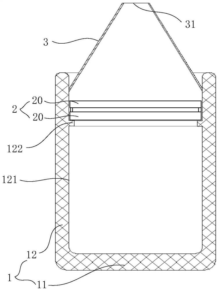
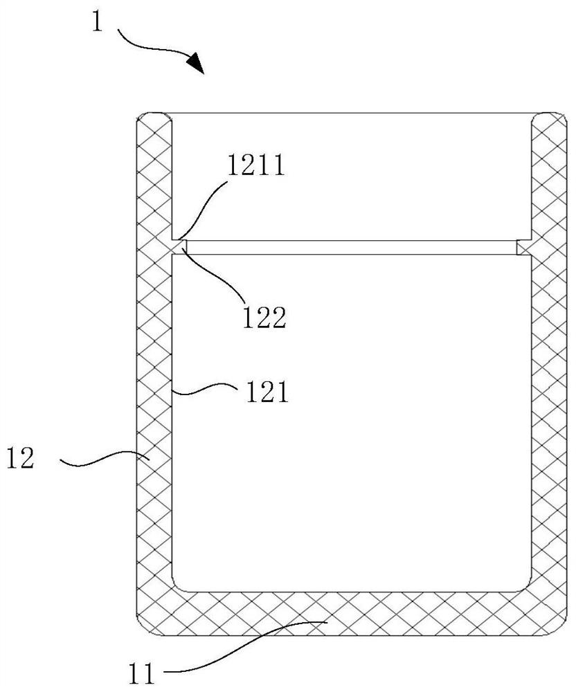
[0039] In some embodiments, referring to figure 2 , the side wall 12 includes a flange 122 extending toward the inside of the accommodating cavity, the flange 122 is located between the bottom wall 11 and the opening of the accommodating cavity, and the flange 122 is annular along the circumferential direction of the accommodating cavity; the supporting surface 1211 is the flange 122 away from the surface of the bottom wall 11. Exemplarily, there can be no less than five millimeters of space between the screen assembly 2 and the coating material, so that the vapor can gather a certain amount in the lower side of the chamber; when the coating material is placed, the height of the coating material is lower than The annular flange 122 prevents the coating material from directly contacting the screen assembly 2 . During the evaporation process, depending on the evaporation material, the temperature in the chamber may reach 800°C or even 1000°C. agents, etc.) are less reliable, ...

Embodiment 2

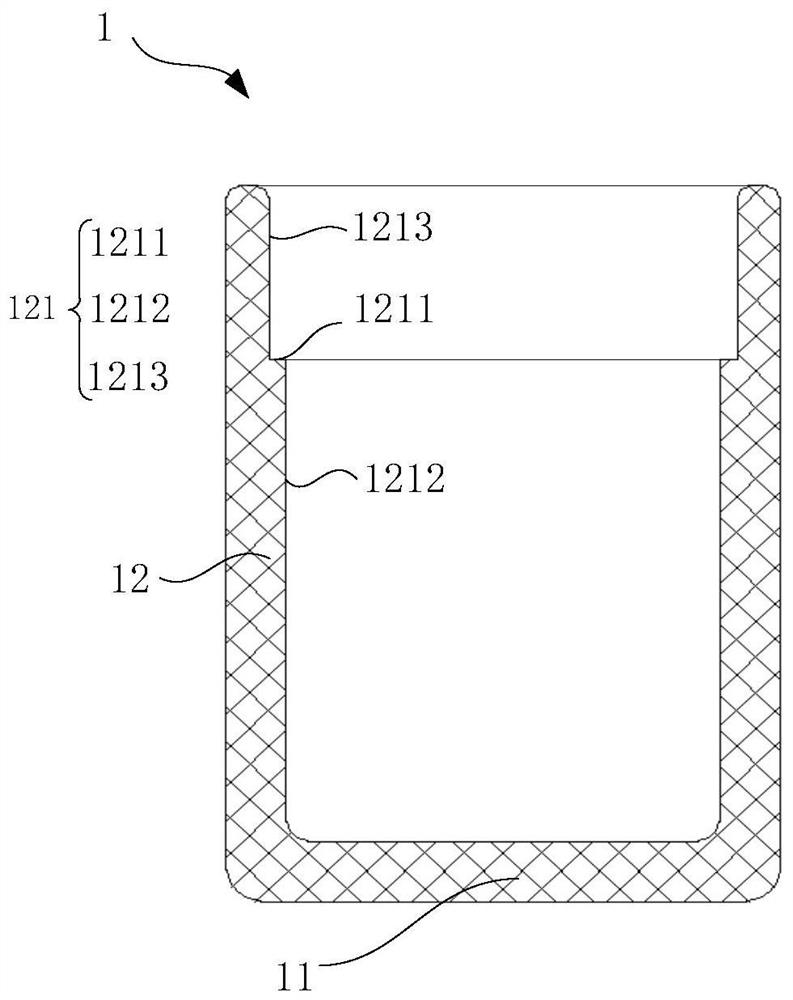
[0042] In some embodiments, referring to image 3 , the first surface 121 further includes a first extension section 1212 and a second extension section 1213 extending in a direction perpendicular to the bottom wall 11, the second extension section 1213 is located on the side of the first extension section 1212 away from the bottom wall 11, and the first The diameter of the extension section 1212 is smaller than the diameter of the second extension section 1213 ; one side of the supporting surface 1211 is connected with the first extension section 1212 , and the other side is connected with the second extension section 1213 . Compared with the method of setting the annular flange 122 on the side wall 12, in this embodiment, the first surface 121 is in a stepped shape, and the side of the side wall 12 away from the bottom wall 11 is in the direction away from the accommodating cavity (toward the outside) Concave, the supporting surface 1211 is a surface parallel to the bottom w...


PUM


Abstract

The invention discloses an evaporation crucible, relates to the technical field of evaporation equipment, and can reduce the speed fluctuation of steam sprayed by a nozzle and reduce the possibility that a coating material is attached to the inner side of the nozzle and continuously grows. The evaporation crucible comprises a crucible body, a screen plate assembly and the nozzle; the crucible bodycomprises a bottom wall and a side wall which is arranged around the bottom wall, the bottom wall and the side wall define a containing cavity with an opening, the surface, close to the containing cavity, of the side wall is a first surface, the first surface comprises a supporting face parallel to the bottom wall; the screen plate assembly comprises at least one screen plate with meshes, the screen plate assembly is abutted with the supporting surface; and the nozzle is mounted at the opening of the containing cavity and is provided with an air spraying hole. The evaporation crucible disclosed by the invention is used for an evaporation process.

Description

technical field [0001] The invention relates to the technical field of evaporation equipment, in particular to an evaporation crucible. Background technique [0002] Evaporation refers to the process of vaporizing and depositing the coating material (or film material) on the surface of the substrate by using a certain heating method under vacuum conditions; it is widely used in the production process of display panels. The evaporation crucible is one of the most important devices in the evaporation process. The evaporation crucible provided in the prior art usually includes a crucible body with a containing cavity and a nozzle arranged at the opening of the crucible body. [0003] In the evaporation crucible in the prior art, as the evaporation process continues, the coating material in the crucible body gradually decreases, the vapor generation rate of the coating material gradually decreases, and the gas pressure in the crucible body decreases, resulting in fluctuations in...

Claims


Application Information

Patent Timeline
IPC IPC(8): C23C14/24
CPCC23C14/243
Inventor 徐天宇黄秦霏肖昂刘洋郭雄飞徐豹朱伍权付佳佳孟德芬易平安赵希瑾贾克飞
Owner BOE TECH GRP CO LTD
Why Eureka
Try Eureka