An electric furnace flue gas waste heat full vaporization, regenerative recovery system and its working method

A flue gas waste heat and recovery system technology, which is applied in the steam generation method using heat carrier, furnace, waste heat treatment, etc., can solve problems such as open welding of welding points, complex system layout, and impact on system operation safety, and increase waste heat absorption , increase steam volume, save system investment and floor space

Active Publication Date: 2017-03-08
山东耀华能源投资管理有限公司
View PDF6 Cites 0 Cited by
  • Summary
  • Abstract
  • Description
  • Claims
  • Application Information

AI Technical Summary

Problems solved by technology

[0004] In terms of safety, the existing waste heat recovery system does not consider the problem of flue gas heat storage, so the convective evaporator in the waste heat recovery system is designed and manufactured according to the peak temperature of the electric furnace flue gas at 1000°C, which requires extremely high processing and manufacturing of the waste heat recovery system, and Frequent fluctuations of flue gas can easily lead to problems such as open welding of welding points, which will have a great impact on the safety of system operation
Moreover, the existing waste heat recovery system is designed to mix water cooling and vaporization cooling, so there are many auxiliary equipment and complex system layout, and it is difficult to arrange multiple media pipelines
[0005] In terms of the quality of the steam recovered by the waste heat recovery system, the current electric furnace flue gas waste heat recovery system is determined by the nature of electric furnace smelting, and the flue gas is in a state of periodic fluctuation. The flue gas has a high temperature period and a low temperature period. Produce steam without continuous steam superheating

Method used


Image

  • An electric furnace flue gas waste heat full vaporization, regenerative recovery system and its working method
  • An electric furnace flue gas waste heat full vaporization, regenerative recovery system and its working method
  • An electric furnace flue gas waste heat full vaporization, regenerative recovery system and its working method

Examples


Embodiment 1

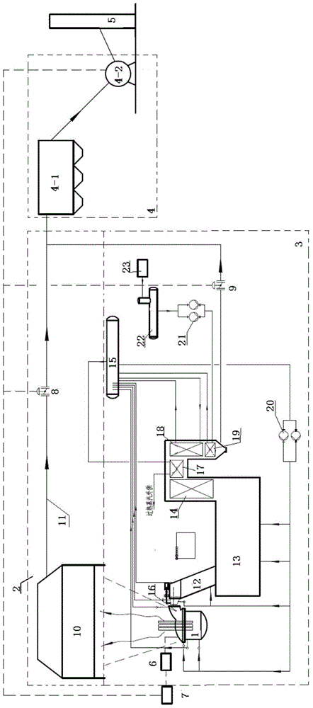
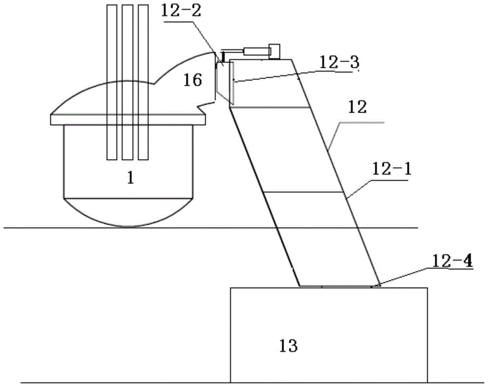
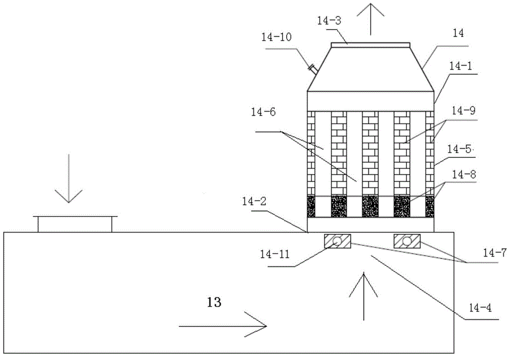
[0049] An electric furnace flue gas waste heat full vaporization, regenerative recovery system, comprising an electric furnace body 1, a flue gas channel 2, a flue gas channel 2 3, a dust collector 4, and a chimney 5; the top flue gas of the electric furnace body 1 The flue gas channel one 2 is connected to the dust collector 4; the internal flue gas of the electric furnace body 1 is connected to the dust collector 4 through the fourth hole 16 of the electric furnace body and the flue gas channel two 3; the flue gas Passage 2 3 includes flow guiding device 12, combustion settling chamber 13, convection heat exchange evaporator 18 and economizer 19 connected in sequence, and intermittent High-temperature flue gas heat storage device 14 and convective heat exchange superheater 17 .

Embodiment 2

[0051] An electric furnace flue gas waste heat full vaporization and regenerative recovery system as described in Example 1, the difference is that in the electric furnace body 1, the flow guide device 12, the combustion settling chamber 13, and the convective heat exchange superheater 17 , The convection heat exchange evaporator 18 and the economizer 19 are respectively equipped with cooling pipes for the furnace body of the electric furnace, cooling pipes for the diversion device, cooling pipes for the combustion and settling chamber, cooling pipes for the convective heat exchange superheater, and convection heat exchangers. The heat evaporator cooling pipe and the economizer cooling pipe; the flue gas channel 2 3 also includes a steam drum 15, and the steam drum 15 is respectively connected with the electric furnace body cooling pipe and the flow guiding device cooling pipe through the circulation pipeline. The pipe is connected with the cooling pipe of the combustion settli...

Embodiment 3

[0053] An electric furnace flue gas waste heat full vaporization and regenerative recovery system as described in Example 2, the difference is that the steam drum 15 is connected with the electric furnace body cooling pipes, the diversion device cooling pipes and the combustion settling chamber cooling pipes A forced circulation pump 20 is arranged on the connected circulation pipeline.

[0054] The flue gas channel 2 3 also includes a boiler feed water pump 21, a deaerator 22 and a boiler feed water device 23, and the inlet end of the economizer cooling pipe is sequentially connected with the boiler feed water pump 21, the deaerator 22 and the boiler feed water device 23, and the outlet end of the economizer cooling pipe is connected with the steam drum 15.


PUM


Abstract

Disclosed is an electric furnace flue gas waste heat complete vaporization and heat accumulation type recovery system. An intermittent high-temperature flue gas heat accumulation device and a heat convection superheater are connected between a combustion settling chamber and a heat convection evaporator in sequence. The intermittent high-temperature flue gas heat accumulation device and the heat convection superheater are additionally arranged in an existing flue gas waste heat recovery system, wherein the intermittent high-temperature flue gas heat accumulation device is applied to a high-temperature flue gas outlet of the combustion settling chamber. When the flue gas flow and temperature fluctuation of an electric furnace happens due to feeding, stable output of the flue gas temperature is achieved through a heat absorption and release reaction of a heat accumulator. When normal smelting is conducted, the temperature of flue gas generated by the electric furnace is high, and part of heat of the flue gas is absorbed by the heat accumulator after the flue gas passes through the intermittent high-temperature flue gas heat accumulation device. When feeding of the electric furnace is conducted, the temperature of flue gas generated by the electric furnace is low, the low-temperature flue gas absorbs the heat in the heat accumulator again after the flue gas passes through the intermittent high-temperature flue gas heat accumulation device, then a stable heat accumulation function is fulfilled, and the situation that high-quality steam is generated by follow-up heating is guaranteed.

Description

technical field [0001] The invention relates to an electric furnace flue gas waste heat full vaporization, regenerative recovery system and a working method thereof, belonging to the technical field of energy utilization in electric furnace smelting. Background technique [0002] Traditional electric furnace flue gas is cooled by circulating water, which not only does not recover waste heat resources but also consumes a lot of electric energy, while the existing electric furnace flue gas waste heat recovery has been implemented. However, at present, there are many problems in the recovery efficiency, safety, matching with the smelting conditions of the electric furnace, and the quality of the steam recovered by the system. These problems have restricted the popularization and development of electric furnace flue gas waste heat technology. [0003] The recovery efficiency of the electric furnace flue gas waste heat recovery system is low. The main problem is that the existin...

Claims


Application Information

Patent Timeline
Patent Type & Authority Patents(China)
IPC IPC(8): F27D17/00F22B1/18
Inventor 李希昌吴京华曹志军陈西明李海凤杨勇
Owner 山东耀华能源投资管理有限公司
Why Eureka
Try Eureka