
Concrete pouring device for water conservancy project building and using method of concrete pouring device

A water conservancy project, concrete technology, applied in the direction of construction, infrastructure engineering, etc., can solve the problems that affect the strength and durability of concrete structures, the quality of concrete structures is difficult to meet the set standards, and the texture of concrete is uneven, so as to improve operating efficiency, The effect of saving manpower and ensuring quality

Active Publication Date: 2021-02-12
杨玉庆
View PDF7 Cites 2 Cited by
  • Summary
  • Abstract
  • Description
  • Claims
  • Application Information

AI Technical Summary

Problems solved by technology

When the staff is resting or not pouring concrete for a long time, due to the long length of the delivery pipe on the cantilever of the concrete pump truck, the aggregate in the concrete will sink in the delivery pipe of the concrete pump truck, resulting in The texture of the concrete is not uniform, which in turn makes it difficult for the quality of the concrete structure to meet the set standards
At the same time, the concrete poured into the steel cage will carry a large number of air bubbles. If the air bubbles are not removed in time, especially in the hot weather outside, some concrete will solidify quickly, so that the air bubbles stay in the concrete permanently, and then Affects the strength and durability of concrete structures

Method used

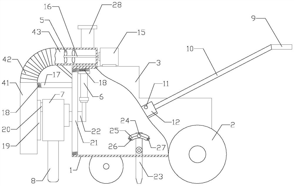
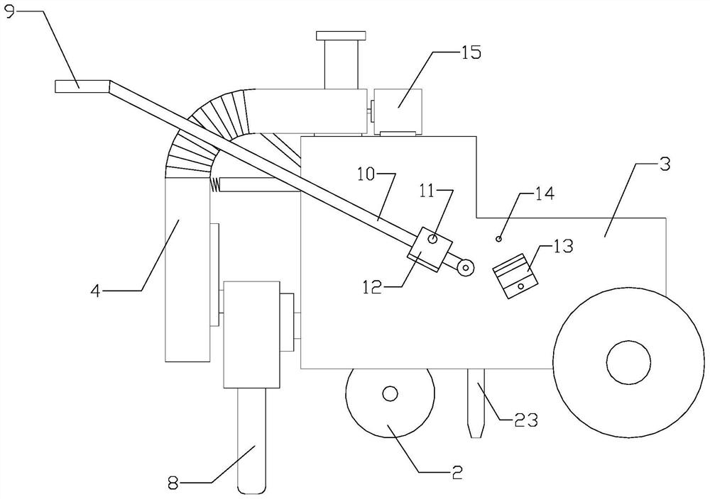
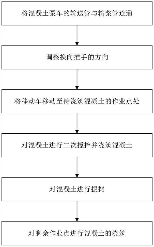

Image

  • Concrete pouring device for water conservancy project building and using method of concrete pouring device
  • Concrete pouring device for water conservancy project building and using method of concrete pouring device
  • Concrete pouring device for water conservancy project building and using method of concrete pouring device

Examples


Embodiment Construction

[0046] The following will clearly and completely describe the technical solutions in the embodiments of the present invention with reference to the accompanying drawings in the embodiments of the present invention. Obviously, the described embodiments are part of the embodiments of the present invention, not all of them. Based on the embodiments of the present invention, all other embodiments obtained by persons of ordinary skill in the art without making creative efforts belong to the protection scope of the present invention.

[0047] Such as Figure 1 to Figure 3As shown, the concrete pouring device for water conservancy construction of the present invention includes a mobile vehicle 1, and the mobile vehicle 1 is provided with a concrete secondary mixing mechanism and a concrete vibrating mechanism;

[0048] The rear side and the lower part of the front side of the mobile vehicle 1 are provided with mobile wheels 2;

[0049] The mobile cart 1 is provided with a cabinet bo...


PUM


Abstract

The invention discloses a concrete pouring device for a water conservancy project building and a using method of the concrete pouring device. A cabinet body is arranged on a mobile vehicle of the device, and a reversing pushing hand is arranged on one side of the cabinet body; a concrete secondary stirring mechanism comprises a slurry conveying pipe used for conveying concrete and a stirring unit,and stirring blades of the stirring unit are located between a slurry outlet and a slurry inlet of the slurry conveying pipe; a concrete vibrating mechanism comprises a lifting unit, a vibrating motor and a vibrating rod, the vibrating motor and the vibrating rod are arranged on the mounting seat, and an output shaft of the vibrating motor is connected with a rotating shaft in the vibrating rod;and the telescopic end of the lifting unit is connected with the mounting base. The method comprises the steps of making a conveying pipe of a concrete pump truck and the slurry conveying pipe communicate; moving the mobile vehicle to an operation point of the concrete to be poured; carrying out secondary stirring on the concrete and pouring the concrete; and carrying out vibration of concrete According to the concrete pouring device, concrete conveyed into an reinforcement cage can be uniform in texture, bubbles in the concrete can be removed in time, and the quality of a concrete structure is guaranteed.

Description

technical field [0001] The application belongs to the technical field of water conservancy engineering construction, and in particular relates to a concrete pouring device for water conservancy engineering buildings and a use method thereof. Background technique [0002] Water conservancy projects are projects built to control and allocate natural surface water and groundwater to achieve the purpose of eliminating harm and rejuvenating profits, also known as water projects. Water is an indispensable precious resource for human production and life, but its natural state does not fully meet human needs. Only by building water conservancy projects can we control water flow, prevent floods, and regulate and distribute water to meet the needs of people's life and production for water resources. Water conservancy projects need to build different types of hydraulic structures such as dams, dikes, spillways, sluices, water inlets, channels, canals, rafts, and fishways to achieve th...

Claims


Application Information

Patent Timeline
Patent Type & Authority Applications(China)
IPC IPC(8): E02D15/02
CPCE02D15/02
Inventor 杨玉庆荆琳侯志毅董战霞赵啟旸王绪关同杰关宏曹刚
Owner 杨玉庆
Learn More