Heading machine and cutting power head device thereof

A power head and power technology, which is applied in the direction of driving devices, transmission parts, cutting machinery, etc., can solve the problems of reduced transmission efficiency, increased space between the reducer and the motor, and increased power transmission loss of the reducer, so as to reduce the occupied space. space, miniaturization, and mechanism simplification

Pending Publication Date: 2021-02-12
CHINA RAILWAY CONSTR HEAVY IND
View PDF0 Cites 1 Cited by
  • Summary
  • Abstract
  • Description
  • Claims
  • Application Information

AI Technical Summary

Problems solved by technology

[0003] The reducer is set in a T shape, and the output end of the motor is connected to the reducer, which increases the space occupied by the reducer and the motor, and has higher requirements for the installation space in the roadheader; the setting of the four-stage reducer structure makes the reducer The internal structure of the reducer is complicated, the cost and manufacturing difficulty are increased, and the loss in the power transmission process of the reducer is increased, which reduces the transmission efficiency

Method used


Image

  • Heading machine and cutting power head device thereof
  • Heading machine and cutting power head device thereof
  • Heading machine and cutting power head device thereof

Examples


Embodiment Construction

[0032] The following will clearly and completely describe the technical solutions in the embodiments of the present invention with reference to the accompanying drawings in the embodiments of the present invention. Obviously, the described embodiments are only some, not all, embodiments of the present invention. Based on the embodiments of the present invention, all other embodiments obtained by persons of ordinary skill in the art without making creative efforts belong to the protection scope of the present invention.

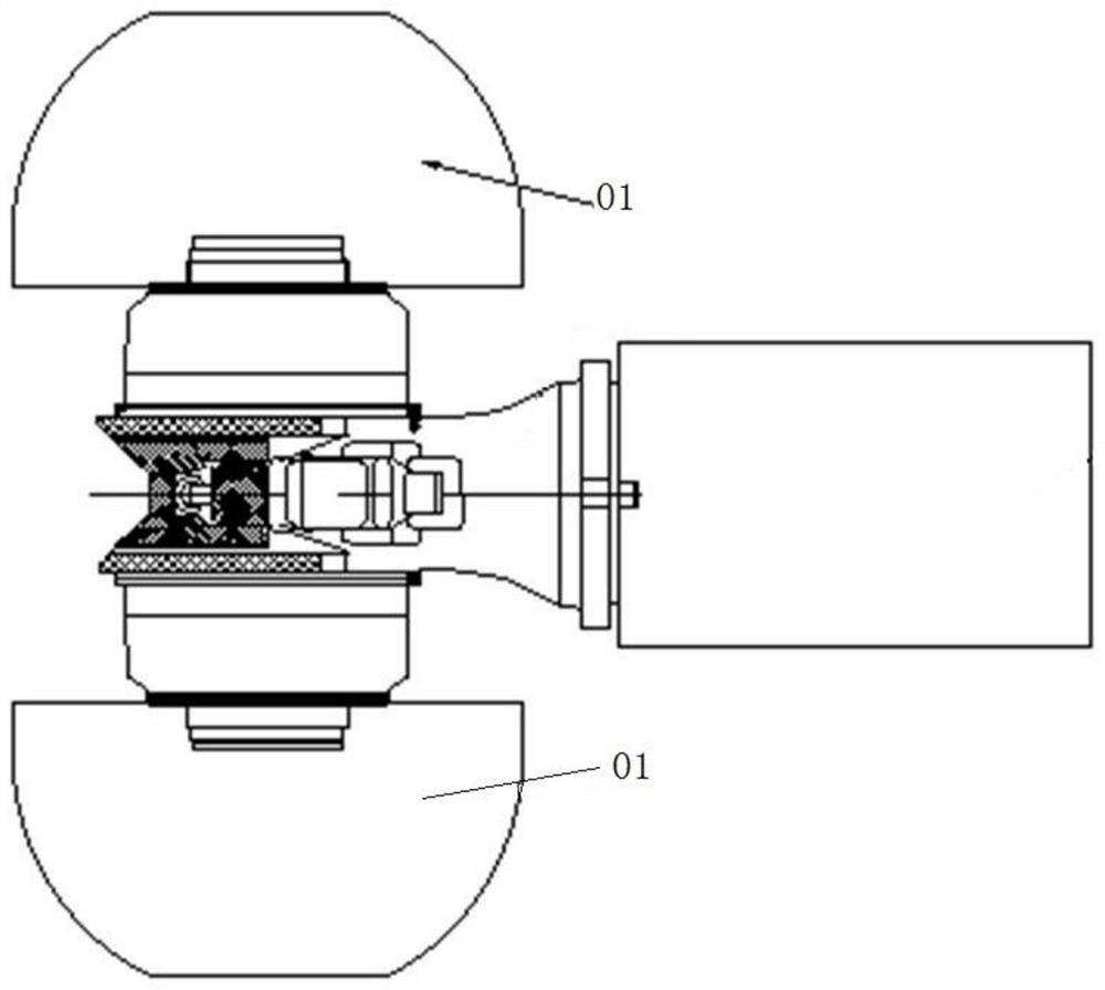
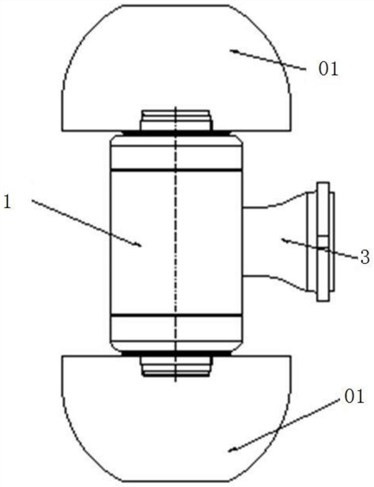
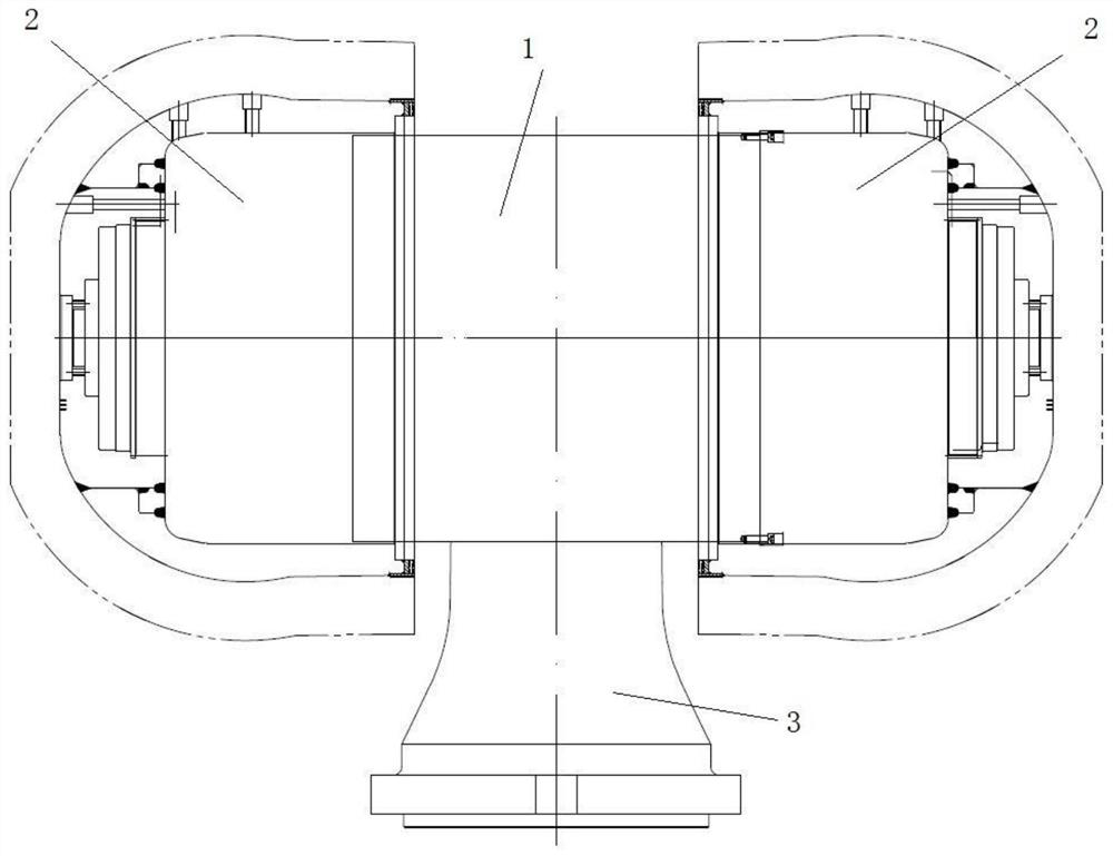
[0033] The core of the present invention is to provide a cutting power head device. By arranging the drive motor and the reducer in a straight line, the drive motor and the reducer are arranged in the same direction, which avoids the direction conversion of the output force of the drive motor. , make full use of the space between the two cutting drums, and reduce the overall space occupied by the cutting power head device. Another core of the present invention...


PUM


Abstract

The invention discloses a heading machine and a cutting power head device thereof. The cutting power head device comprises a driving motor, speed reducers and cutting rollers. The driving motor is used for providing power for the rotation of the cutting rollers. The speed reducers are used for converting the high-rotating-speed low-torque power output by the driving motor into low-rotating-speed high-torque power and transmitting the low-rotating-speed high-torque power to the cutting rollers. The cutting roller are connected with the speed reducers and are driven by the driving motor to tunnel and excavate. The output end of the driving motor is connected with the speed reducers, and the driving motor and the speed reducers are arranged in a linear mode. According to the cutting power head device, the speed reducers and the driving motor are arranged in the same direction, the direction of output force does not need to be changed, arrangement of bevel gear sets in the speed reducers is avoided, and the mechanisms of the speed reducers are simplified; and the space between the cutting rollers can be better utilized, the space occupied by the speed reducers and the driving motor asa whole is reduced, and miniaturization of the cutting power head device is facilitated.

Description

technical field [0001] The invention relates to the technical field of excavation equipment, and more specifically, relates to a cutting power head device. In addition, the present invention also relates to a roadheader comprising the above-mentioned cutting power head device. Background technique [0002] Such as figure 1 As shown, in the existing horizontal-axis cantilever roadheader products, the cutting mechanism is composed of three parts: the drive motor, the reducer and the cutting drum 01. The structure of the reducer is a T-shaped structure, and the T-shaped structure of the reducer There are connecting parts for connecting with the driving motor and connecting parts respectively connected with the two cutting drums 01; the reducer is four-stage reduction, one of which is parallel shaft transmission, the second is bevel gear transmission, and the third and fourth stages It is a planetary gear transmission, which converts the input power of high speed and low torqu...

Claims


Application Information

Patent Timeline
IPC IPC(8): E21C31/02E21C25/06F16H57/08
CPCE21C25/06E21C31/02F16H57/08F16H2057/02034F16H2057/02086
Inventor 刘飞香刘金书张贤福朱坤杰刘光辉周昊丁羽锋
Owner CHINA RAILWAY CONSTR HEAVY IND
Why Eureka
Try Eureka