
Ocean current power generation equipment

A power generation device and ocean current technology, applied in ocean energy power generation, electromechanical devices, hydroelectric power generation, etc., can solve problems such as slow speed, poor absorption effect of ocean kinetic energy, and low operating efficiency of generators

Active Publication Date: 2021-02-12
太仓治誓机械设备科技有限公司
View PDF7 Cites 0 Cited by
  • Summary
  • Abstract
  • Description
  • Claims
  • Application Information

AI Technical Summary

Problems solved by technology

[0002] As we all know, ocean current power generation mainly uses the flow of seawater under the sea to drive the operation of power generation equipment and generate electricity. The existing ocean current power generation equipment is mainly composed of an impeller, a generator, and a base. The ocean current drives the impeller installed on the generator to rotate. The impeller drives the generator to run and generate electric energy. When this kind of equipment is used, due to the relatively simple structure and single function of the equipment, the speed at which the ocean current pushes the impeller to rotate is relatively slow, the operating efficiency of the generator is low, and the energy absorption rate is poor. The reverse blocking effect of the ocean current is strong, and the equipment cannot play a good drainage effect on the ocean current, and it is easy to make the ocean current bypass the equipment and continue to flow, resulting in poor absorption effect of the equipment on the ocean flow energy

Method used


Image

  • Ocean current power generation equipment
  • Ocean current power generation equipment
  • Ocean current power generation equipment

Examples


Embodiment Construction

[0019] The specific implementation manners of the present invention will be further described in detail below in conjunction with the accompanying drawings and embodiments. The following examples are used to illustrate the present invention, but are not intended to limit the scope of the present invention.

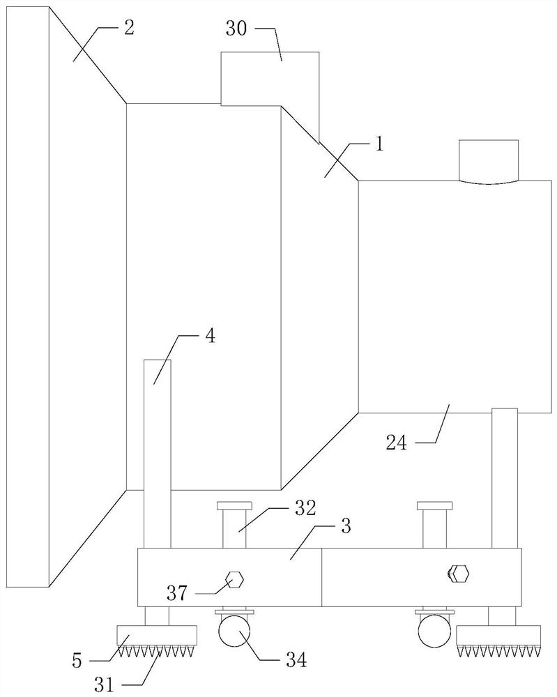
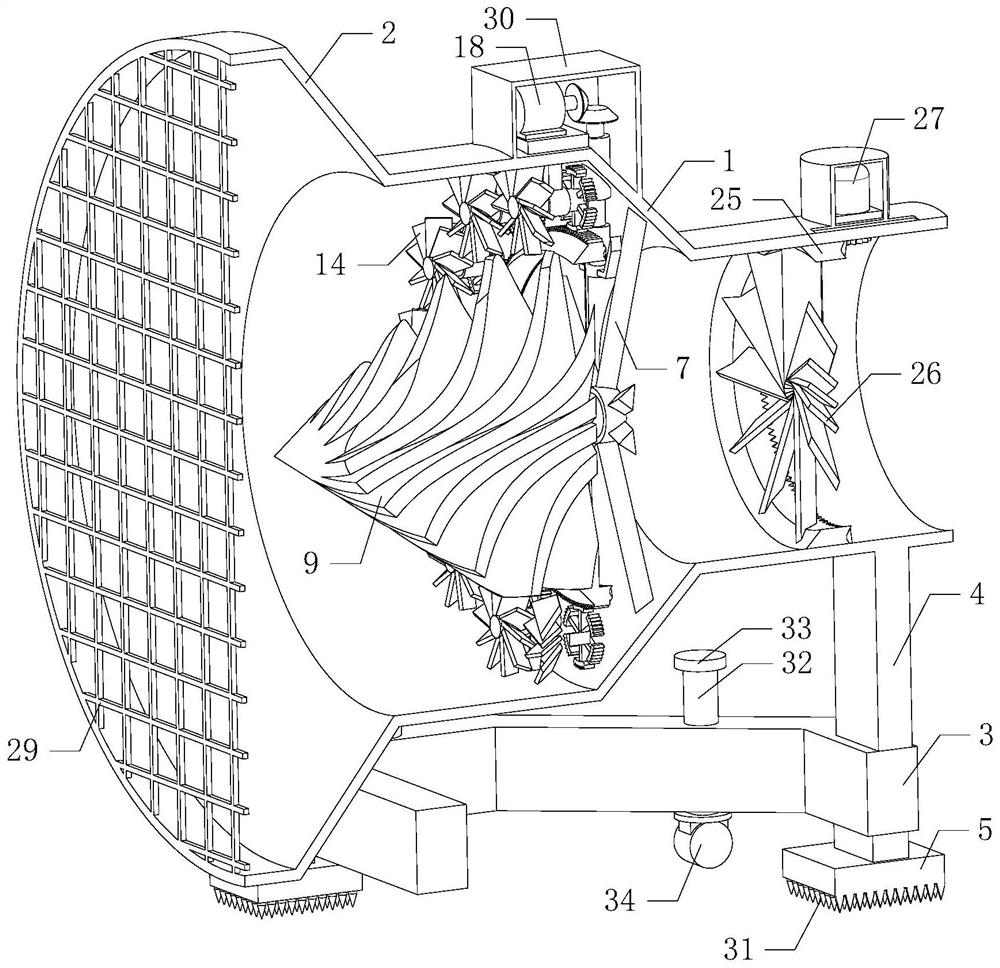
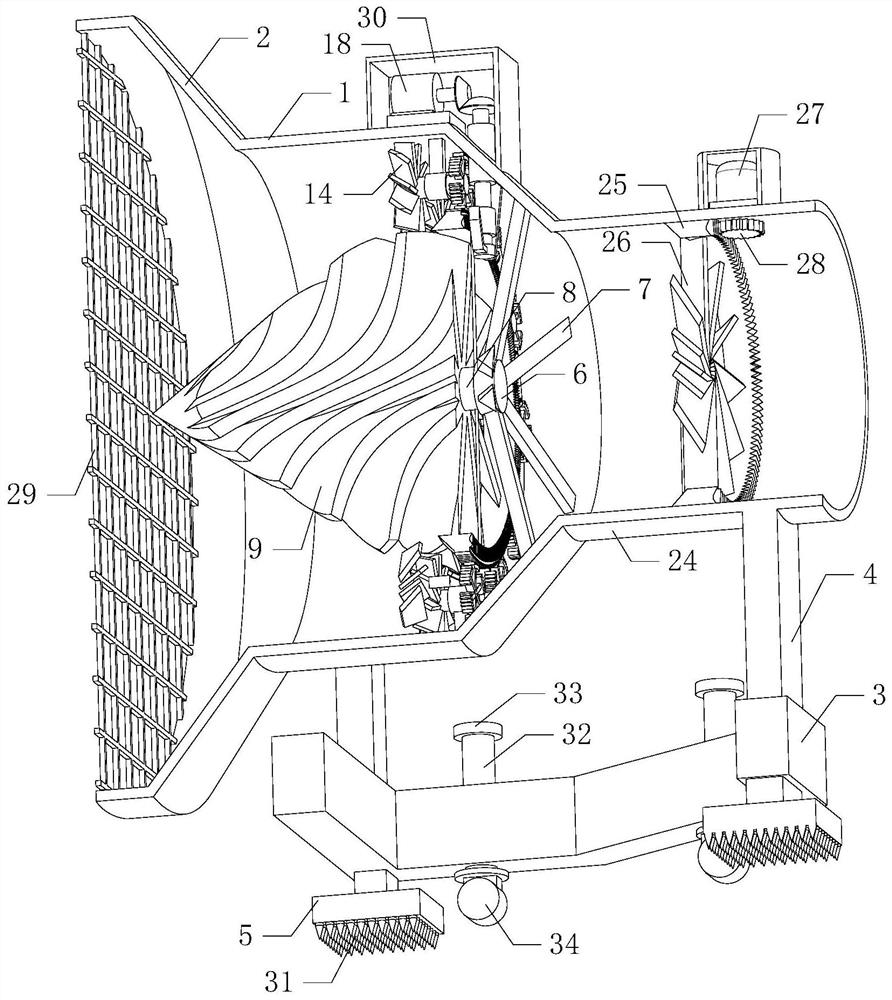
[0020] Such as Figure 1 to Figure 5 As shown, a kind of marine ocean current power generation device of the present invention, when it is working, the equipment is placed on the seabed, the external ocean current can enter the power cylinder 1 through the flow gathering bucket 2, and the flow gathering bucket 2 can carry out the flow collection process on the ocean current, It is convenient to gather the kinetic energy in the ocean current. The ocean current entering the power cylinder 1 can drive multiple sets of spiral deflectors 9 on the power shaft 8 to rotate, and multiple sets of spiral deflectors 9 drive the power ring 10 to rotate. Since multiple sets of spiral de...


PUM


Abstract

The invention relates to the technical field of new energy equipment, in particular to ocean current power generation equipment. By performing power generation and utilization on ocean current, the functional diversity of equipment is effectively improved, the running speed of the equipment is improved, the electric energy output is effectively improved, the energy absorption rate is improved, meanwhile, the equipment can perform an effective drainage effect on the ocean current, reverse choked flow acting force of equipment on the ocean current is reduced, the ocean current can smoothly enterthe equipment conveniently, the ocean current kinetic energy absorption effect is improved, the equipment operation efficiency is improved, and practicability and reliability are improved. The equipment comprises a power cylinder, a flow gathering hopper, a lower supporting ring, three supporting rods, three ground feet and a fixing disc, the flow gathering hopper is installed on the left side ofthe power cylinder, the right side of the power cylinder communicates with a secondary energy absorption device, the lower supporting ring is located below the power cylinder and fixed to the power cylinder and the secondary energy absorption device through the three supporting rods, and the three ground feet are evenly installed at the bottom of the lower supporting ring.

Description

technical field [0001] The invention relates to the technical field of new energy equipment, in particular to an ocean current power generation device. Background technique [0002] As we all know, ocean current power generation mainly uses the flow of seawater under the sea to drive the operation of power generation equipment and generate electricity. The existing ocean current power generation equipment is mainly composed of an impeller, a generator, and a base. The ocean current drives the impeller installed on the generator to rotate. The impeller drives the generator to run and generate electric energy. When this kind of equipment is used, due to the relatively simple structure and single function of the equipment, the speed at which the ocean current pushes the impeller to rotate is relatively slow, the operating efficiency of the generator is low, and the energy absorption rate is poor. The reverse blocking effect of the ocean current is strong, and the equipment cann...

Claims


Application Information

Patent Timeline
IPC IPC(8): F03B13/26F03B3/18F03B3/12F03B11/00F03B11/08H02K7/18
CPCF03B13/264F03B3/18F03B3/12F03B11/00F03B11/08H02K7/1823Y02E10/20Y02E10/30
Inventor 吴禹凡高洪庆
Owner 太仓治誓机械设备科技有限公司
Learn More