
Microneedle type wire connecting device

A technology of wire connection and microneedle, which is applied in the direction of conductive connection, connection, connection insulation, etc., can solve problems such as insecurity, burning failure, and oxidation of the connection, and achieve high mechanical strength and hardness, prevent distortion and deformation, and reduce production costs. low effect

Pending Publication Date: 2021-02-12
STATE GRID CORP OF CHINA +1
View PDF0 Cites 0 Cited by
  • Summary
  • Abstract
  • Description
  • Claims
  • Application Information

AI Technical Summary

Problems solved by technology

This connection method has the following problems: it is extremely unsafe to operate with electricity at high altitude, it requires a high technical level of the operator, the mechanical tensile strength cannot meet the requirements, and in the "binding method" of the main and auxiliary wires, the electrical The conduction ability is also difficult to meet the requirements, so there are often poor contacts between the main wire and the auxiliary wire, and even oxidation and burning faults at the connection
This connection method is simple, but there are also the following problems: the mechanical tensile strength, conductivity or connection impedance between the main and auxiliary wires are difficult to meet the specified requirements, and the main and auxiliary wires must be bare wires

Method used


Image

  • Microneedle type wire connecting device
  • Microneedle type wire connecting device
  • Microneedle type wire connecting device

Examples


Embodiment

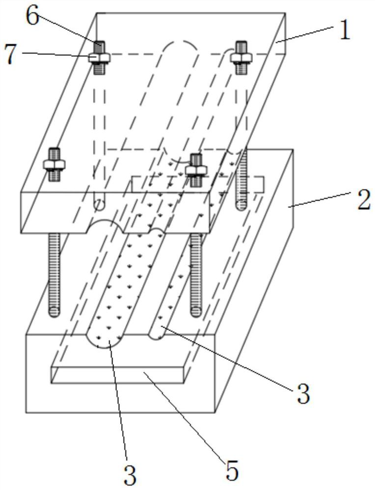
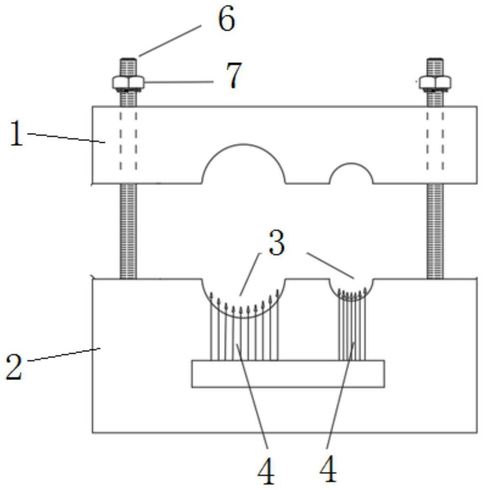
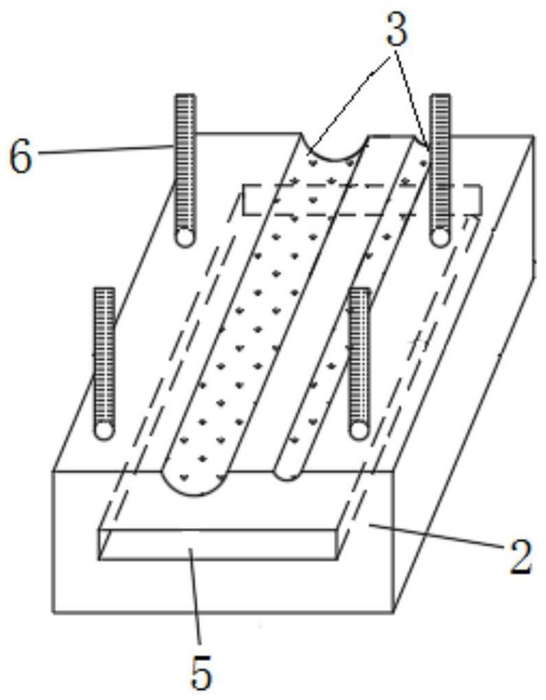
[0034] Such as Figure 1~3 The microneedle wire connection device shown includes an upper casing 1 , a lower casing 2 , four bolts 6 and matching nuts 7 , a conductor 5 and several conductive alloy microneedles 4 . Both the upper casing 1 and the lower casing 2 adopt a rectangular structure made of insulating engineering plastics, and the two are connected by four bolts 6 evenly distributed at the four corners. The wire groove 3 on the lower casing 2 is a half groove body structure, which is arranged opposite to the half groove body provided on the upper casing 1, and the two half groove bodies can be combined into a whole groove body adapted to the wire. The conductor 5 built in the lower case 2 is a plate-like structure, and its length direction is consistent with the axis direction of the wire groove 3 .

[0035] When the electric wire and cable need to be connected, the main wire and the guidance wire are respectively inserted in the two wire grooves 3 . Rotate the nut 7...


PUM

PropertyMeasurementUnit
diameteraaaaaaaaaa
tensile strengthaaaaaaaaaa
hardnessaaaaaaaaaa

Abstract

The invention discloses a microneedle type wire connecting device, which comprises an upper shell, a lower shell, a plurality of conductive alloy microneedles and an electric conductor, wherein the upper shell and the lower shell are connected through a fastener; a plurality of wire grooves are formed in the lower shell, to-be-connected wires are placed in the wire grooves, and the lower surface of the upper shell can tightly press the wires; the electric conductor is arranged in the lower shell; the conductive alloy microneedles are vertically arranged, the lower ends of the conductive alloymicroneedles are fixedly connected with the electric conductor, the upper ends of the conductive alloy microneedles extend into the wire grooves, and the conductive alloy microneedles are inserted into the bare conductors of the wires after piercing the insulating layers of the wires. The beneficial effects of the invention are that: the conductive alloy microneedles are made of a high-strength alloy material, are inserted into the bare conductors after penetrating into the insulating layers of the wires, and are in good contact with the bare conductors, thereby guaranteeing the electrical contact area of the conductive alloy microneedles with the main wire and the auxiliary wire, and improving the electrical conduction capability between the main wire and the auxiliary wire.

Description

technical field [0001] The invention relates to wire connection technology, in particular to a microneedle wire connection device. Background technique [0002] In power engineering, especially power line engineering, the connection of two insulated wires or bare wires is very common. When two wires are connected, under the condition of ensuring the electrical safety of the operator, the mechanical tensile strength, electrical conduction capacity and electrical insulation strength between the two wires should meet the requirements. For the convenience of description, the wire to be incorporated is called the main wire, and the wire to be incorporated is called the tutor wire. At present, there are the following three methods for connecting the main and auxiliary wires on site. [0003] The first connection method is: the main wire is the wire that is energized and running, and the auxiliary wire is the wire to be connected to the energized line (the wire that is about to b...

Claims


Application Information

Patent Timeline
Patent Type & Authority Applications(China)
IPC IPC(8): H01R4/2406H01R4/2475H01R4/58H01R4/70H01R11/07
CPCH01R4/2475H01R4/58H01R4/70H01R11/07H01R4/2406
Inventor 李国胜罗福玲洪雯古小琴陶建武赵然霍明万琦许嘉诚
Owner STATE GRID CORP OF CHINA
Learn More