
Laser pulse width compression system with preset space chirp

A space chirp, preset space technology, applied in the field of laser science, can solve problems such as beam side leakage, energy load limitation, damage, etc.

Pending Publication Date: 2021-02-12
SHANGHAI INST OF OPTICS & FINE MECHANICS CHINESE ACAD OF SCI
View PDF4 Cites 6 Cited by
  • Summary
  • Abstract
  • Description
  • Claims
  • Application Information

AI Technical Summary

Problems solved by technology

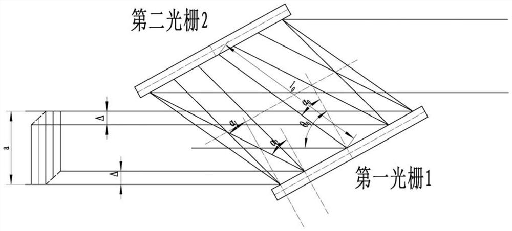
Otherwise, the side leakage of the beam will increase the loss. Not only the large energy leakage may cause damage to the surrounding components, but also the main beam is diffracted by the cutting edge of the grating, which will change the pulse width of the edge area of ​​the near-field spot and affect the optical quality of the far and near field of the beam.
This makes the prior art have to restrict the laser beam aperture, unable to make full use of the grating area on the first grating 1 and the fourth grating 4, and the energy load is limited

Method used


Image

  • Laser pulse width compression system with preset space chirp
  • Laser pulse width compression system with preset space chirp
  • Laser pulse width compression system with preset space chirp

Examples


Embodiment Construction

[0037] The present invention will be further described below in conjunction with the accompanying drawings and embodiments.

[0038] Figure 4 It is a structural schematic diagram of Embodiment 1 of the laser pulse width compression system with preset spatial chirp in the present invention. It can be seen from the figure that the laser pulse width compression system with preset spatial chirp in the present invention includes a spatial chirp generator 5, a first optical telescopic beam expander 6, a near-field spot corrector 7, and a second optical telescopic beam expander 8. The first laser energy amplifier 9 , the terminal optical telescopic beam expander 10 and the spatially chirped grating compressor 11 .

[0039] This embodiment is applied to a Ti:Sapphire chirped pulse amplification system in the 800nm ​​band, using a grating with a rectangular working surface size of 555*995mm, which is expected to output a peak power of more than 25PW.

[0040] Assume that the beam sp...


PUM


Abstract

A laser pulse width compression system with preset space chirp comprises: a space chirp generator; and a first optical telescopic beam expander, a near-field light spot corrector, a second optical telescopic beam expander, a first laser energy amplifier,..., an Nth optical telescopic beam expander, an Mth laser energy amplifier,..., a tail end optical telescopic beam expander and a space chirp type grating compressor which are sequentially arranged in the direction of space chirp laser generated by the space chirp generator. The space chirp generator is used for enabling different spectral components of the laser pulse to be distributed at different positions of the cross section of the light beam to form a specific spatial chirp proportion. The superficial area of the grating can be fullyutilized, the energy load of the grating compressor is remarkably increased, the light beam energy loss of the grating compressor caused by the limited grating size is reduced, and then the upper limit of the output peak power of the laser chirped pulse amplifying device is improved.

Description

technical field [0001] The invention relates to the field of laser science, to the research and application field of laser chirped pulse amplification technology capable of outputting high-energy femtosecond pulses, and is a laser pulse width compression system especially suitable for wide-spectrum high-energy laser chirped pulses. Background technique [0002] Chirped Pulse Amplifiers (CPAs for short) can realize the energy amplification and femtosecond output of laser pulses. experiment platform. "Laser chirped pulse" means that the laser pulse is chirped in the time domain—that is, the spectral wavelength at different time positions of the pulse is also different. "Super strong and ultra short" means that the laser pulse width is as short as less than 100 femtoseconds (femtoseconds, that is, 10 -15 s, abbreviated as fs), the peak power (energy divided by the pulse width) is as high as 100 terawatts or more (terawatts, that is, 10 12 W, abbreviated as TW). [0003] Las...

Claims


Application Information

Patent Timeline
IPC IPC(8): H01S3/00H01S3/08H01S3/082
CPCH01S3/08009H01S3/0057H01S3/0826
Inventor 王乘王丁刘星延吴分翔冷雨欣李儒新
Owner SHANGHAI INST OF OPTICS & FINE MECHANICS CHINESE ACAD OF SCI
Learn More