
Method for whitening colored noise in a communication system

a communication system and color-whitening technology, applied in the field of communication systems, can solve problems such as interfering signals in high-speed data communication systems, home networking systems, cable modem systems, etc., and achieve the effect of improving data throughput rates and improving the properties of inputs

Inactive Publication Date: 2002-09-12
AVAGO TECH INT SALES PTE LTD
View PDF2 Cites 66 Cited by
  • Summary
  • Abstract
  • Description
  • Claims
  • Application Information

AI Technical Summary

Benefits of technology

[0015] The filtering operations of the present invention may be deployed within receiver sections of home phone line network devices. When deployed in these devices, the filtering operations remove interfering signals and whiten colored noise present at the input of the receiver. Each of these operations improves the properties of the input and allows data throughput rates to be increased.

Problems solved by technology

Further, some of these high-speed data communication systems share similar operational drawbacks.
Home networking systems and cable modem systems, for example, are both subject to interfering signals that are coupled on media that carry communication signals.
These intermittent narrowband interfering signals unintentionally couple to the shared coaxial cables via deficiencies in shielding and / or other coupling paths.
Thus, when the interfering signal first reappears, the cancellation filter cannot fully compensate for the interfering signal.
Because many interfering signals are intermittent, the presence of these intermittent signals reduces the bandwidth that is supportable upon the coaxial media during the time period required for the cancellation filter to adapt.
Further, because the interfering signals oftentimes vary in strength while present, the adaptive cancellation filter most often times does not fully remove the interfering signal.
Overlapping adjacent channel signals cause another source of interference for the desired signal because they often produce interfering signals in the band of the desired signal.
For example, a TDMA signal that resides in an adjacent channel and that turns on and off may have side lobes that overlap and interfere with the desired signal.
In many operational conditions, typical fluctuations in the strength of interfering signals cause conventional cancellation filters to provide insufficient cancellation.
Home phone line networks suffer from similar operational difficulties.
UTP wiring is susceptible to RFI coupling because of its construction and RFI sources, such as HAM radio transmitters, couple significant interfering signals onto the UTP wiring.
Further, because Plain Old Telephone System (POTS) equipment shares the UTP wiring with the coupled data communication equipment, signals produced by the POTS equipment and introduced by the telephone network introduce additional interfering signals that affect data communications on the home phone line network.

Method used


Image

  • Method for whitening colored noise in a communication system
  • Method for whitening colored noise in a communication system
  • Method for whitening colored noise in a communication system

Examples


first embodiment

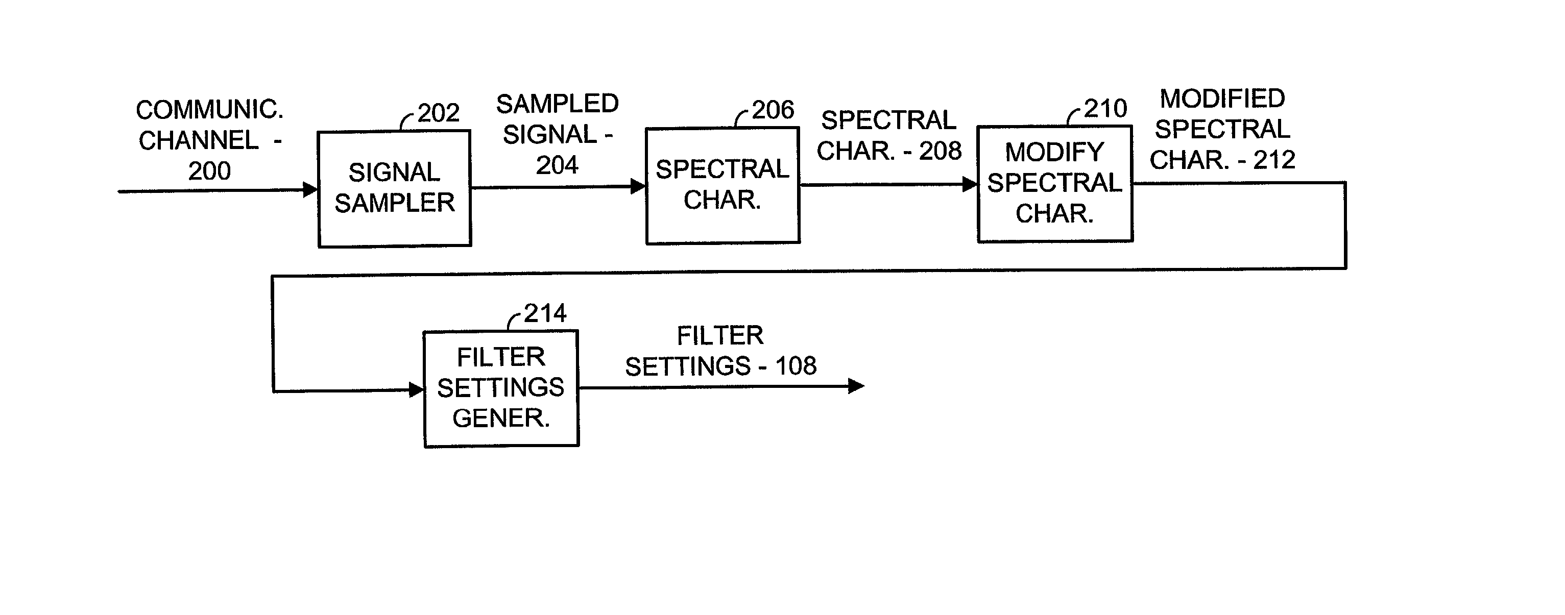
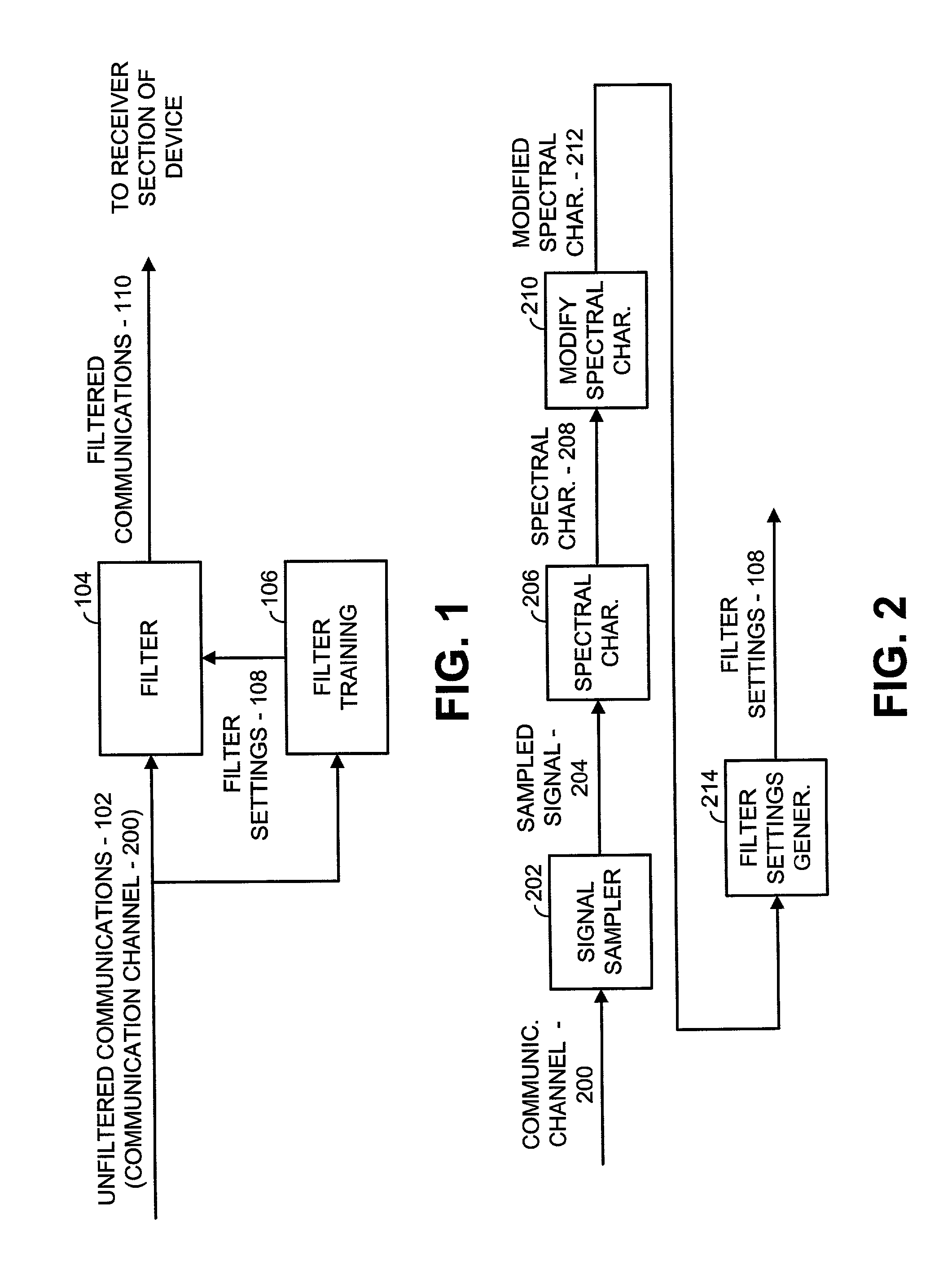
[0037] FIG. 1 is a simplified block diagram illustrating a narrow band interference cancellation filter (ICF) used in accordance with the principles of the present invention. According to the present invention, incoming unfiltered communications 102 are received on a communication channel and filtered using filter 104 to produce filtered communications 110. Filter settings 108, generated by filter training block 106, when applied to filter 104 remove narrow band interfering signals from the communication channel to produce the filtered communications 110. Thus, during normal operations, the filtered communications 110 are provided to the receiver section of a device in which the ICF resides. Because of the filtering operations of the present invention, the receiver is better able to operate on a signal of interest (desired signal) contained in the filtered communications 110 to extract data contained therein. The signal of interest, in most embodiments, is a carrier in a particular ...


PUM


Abstract

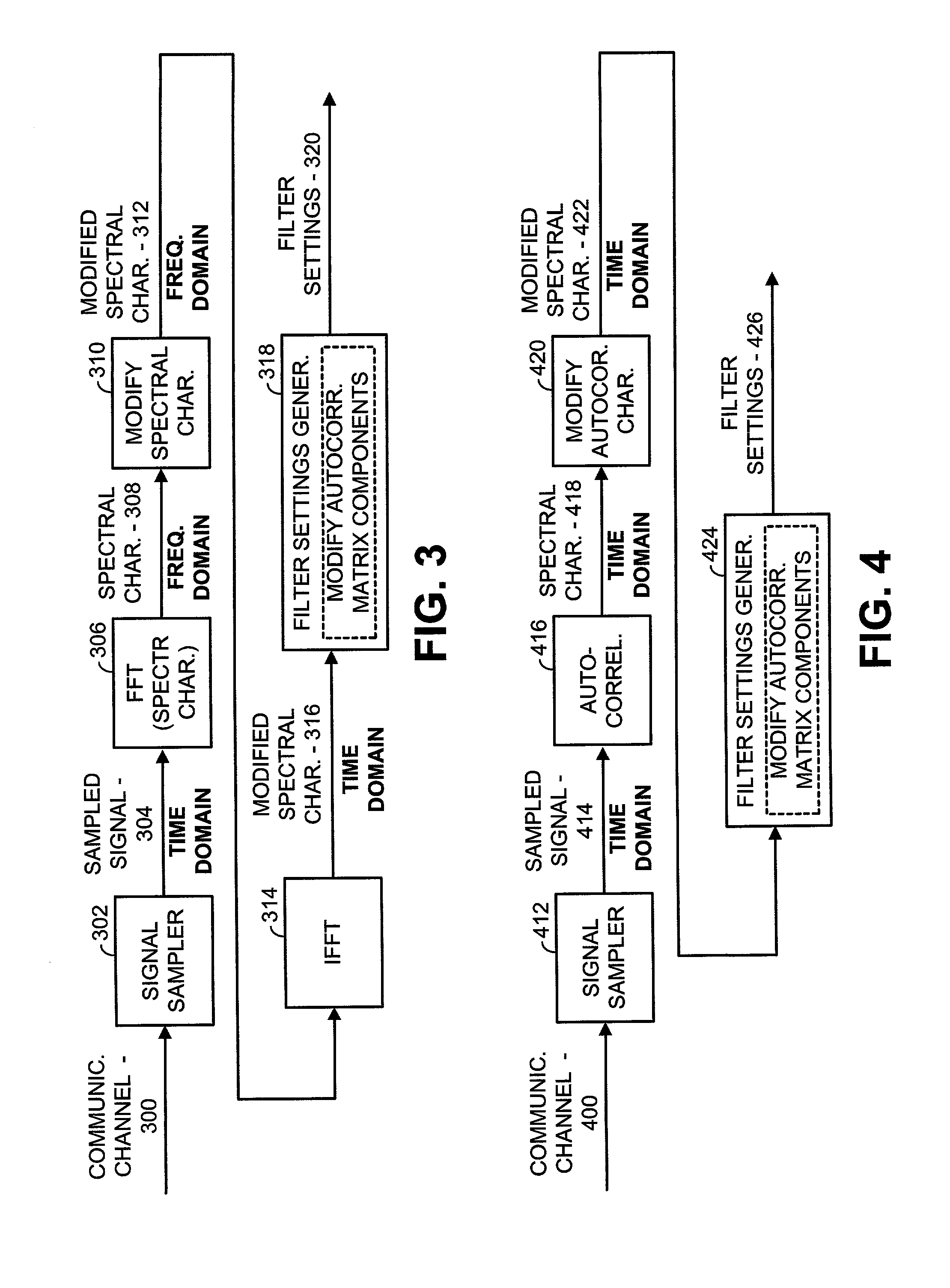
A filter settings generation operation includes sampling colored noise present at the input of a receiver to produce a sampled signal. The sampled signal is spectrally characterized across a frequency band of interest to produce a spectral characterization of the sampled signal. This spectral characterization may not include a signal of interest. The spectral characterization is then modified to produce a modified spectral characterization. Filter settings are then generated based upon the modified spectral characterization. Finally, the input present at the receiver is filtered using the filter settings when the signal of interest is present to whiten colored noise that is present with the signal of interest. In modifying the spectral characterization, pluralities of spectral components of the spectral characterization are independently modified to produce the modified spectral characterization. Modifications to the spectral characterization may be performed in the frequency domain and / or the time domain. Particular modifications include amplifying spectral components, weighting spectral components based upon prior spectral components, and averaging spectral components with prior spectral components.

Description

CROSS REFERENCES TO RELATED APPLICATIONS[0001] This application claims priority to U.S. Provisional Application Serial No. 60 / 262,380, filed Jan. 16, 2001, and to U.S. Regular application Ser. No. 09 / 878,730, filed Jun. 11, 2001, both of which are incorporated herein by reference in their entirety.FIELD OF THE INVENTION[0002] The present invention relates generally to communication systems, and more particularly to interference mitigation and noise whitening in such communication systems.BACKGROUND OF THE INVENTION[0003] The structure and operation of high-speed data communication systems are generally known. Such high-speed data communication systems employ various media and / or wireless links to support the transmission of high-speed data communications. Particular embodiments of high-speed communication systems include, for example, cable modem systems, home networking systems, wired local area networks, wired wide area networks, wireless local area networks, satellite networks, e...

Claims


Application Information

Patent Timeline
Patent Type & Authority Applications(United States)
IPC IPC(8): H04B1/10H04B1/12H04L1/00H04L25/03
CPCH04B1/1036H04B1/123H04L1/0001H04L25/03006
Inventor OJARD, ERICBAGCHI, AMIT GOUTAM
Owner AVAGO TECH INT SALES PTE LTD
Learn More