
Combined V-shaped demagnetization-preventing permanent magnet motor rotor

A permanent magnet motor, combined technology, applied in the direction of magnetic circuit rotating parts, synchronous machines, electrical components, etc., can solve the problems of magnetic steel demagnetization hidden danger, poor overload capacity, demagnetization and magnetic field distortion, etc. The effect of steel demagnetization, improving overload capacity and overload multiple

Inactive Publication Date: 2021-02-12
SHANGHAI CHUANYE ELECTRIC MACHINE
View PDF0 Cites 0 Cited by
  • Summary
  • Abstract
  • Description
  • Claims
  • Application Information

AI Technical Summary

Problems solved by technology

At present, there are still technical bottlenecks in the development of permanent magnet synchronous motors (PMSM) with high overload capacity and anti-demagnetization for electric vehicles. There are hidden dangers of magnetic steel demagnetization, low overload capacity, slow response, low power density and torque density. Defects such as poor reliability and reduced operating performance make it difficult to meet the requirements
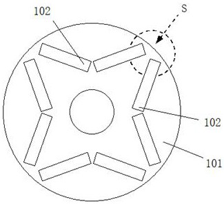
[0003] like image 3 As shown, on the rotor iron core 101 of the existing V-shaped permanent magnet synchronous motor, the magnetic steel 102 arranged in V shape is all made of a single magnetic steel, and the magnetic steel 102 and the pole shoe (rotor core) form a permanent magnetic pole, and the rotor iron The interpolar area S of the core 101 is the armature reaction demagnetization dangerous area; when there is no current passing through the armature winding, the magnetic field formed by the permanent magnet poles is the main magnetic field; when there is current passing through the armature winding, the armature The winding generates an armature magnetic field, and the action of the armature magnetic field on the main magnetic field will distort the main magnetic field and generate an armature reaction, thereby appearing the armature magnetomotive force, which will distort the air gap magnetic field between the stator and rotor (that is, the armature response); when the existing V-type motor rotor is loaded, the armature reaction will cause the magnet to demagnetize, especially when the demagnetization and magnetic field distortion at both ends of the magnet are strong during overload, the armature reaction demagnetization danger zone S is at the two ends of the magnet, It will even cause irreversible demagnetization at both ends, which will lead to increased iron loss and copper loss of the motor, reduced efficiency, increased temperature rise, and reduced safety performance. Therefore, the overload capacity of the existing V-type motor rotors is poor.

Method used


Image

  • Combined V-shaped demagnetization-preventing permanent magnet motor rotor
  • Combined V-shaped demagnetization-preventing permanent magnet motor rotor
  • Combined V-shaped demagnetization-preventing permanent magnet motor rotor

Examples


Embodiment Construction

[0016] The embodiments of the present invention are described in further detail below in conjunction with the accompanying drawings, but the present embodiments are not intended to limit the present invention. All similar structures and similar changes of the present invention should be included in the scope of protection of the present invention. The commas in all indicate the relationship between and.

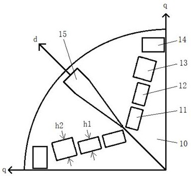
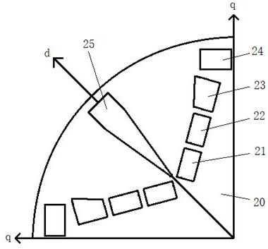
[0017] Such as figure 1 As shown, a combined V-type anti-demagnetization permanent magnet motor rotor provided by the first embodiment of the present invention includes a rotor core 10, and a plurality of permanent magnet units are arranged on the rotor core 10, and each permanent magnet The units are arranged symmetrically around the axis of the rotor core, which is characterized by:

[0018] The permanent magnet unit includes a V-shaped magnetic steel combination, the V-shaped magnetic steel combination is composed of two inline composite magnets, and the two inline compo...


PUM


Abstract

The invention discloses a combined V-shaped demagnetization-preventing permanent magnet motor rotor and relates to the technical field of motors. The rotor comprises a rotor iron core, a plurality ofpermanent magnet units are arranged on the rotor iron core, the permanent magnet units are symmetrically arranged around the axis of the rotor iron core, and each permanent magnet unit comprises a V-shaped magnetic steel combination. Each V-shaped magnetic steel combination is composed of two pieces of linear composite magnetic steel, the two pieces of linear composite magnetic steel are arrangedon the two sides of the d axis respectively, and the two pieces of linear composite magnetic steel are arranged in a V shape; each piece of line-shaped composite magnetic steel is composed of three magnetic steel segments, the three magnetic steel segments are arranged in a line shape, and the thickness of the magnetic steel segment close to the q axis is larger than that of the other two magneticsteel segments. The rotor provided by the invention is high in overload capacity.

Description

technical field [0001] The invention relates to motor technology, in particular to a combined V-type anti-demagnetization permanent magnet motor rotor technology. Background technique [0002] Permanent magnet synchronous motors are widely used in electric vehicles. The motor is one of the cores of the electric drive system. The comprehensive performance of the motor directly affects the performance of electric vehicles. At present, there are still technical bottlenecks in the development of permanent magnet synchronous motors (PMSM) with high overload capacity and anti-demagnetization for electric vehicles. There are hidden dangers of demagnetization of magnetic steel, low overload capacity, slow response, low power density and torque density. Defects such as poor reliability and reduced operating performance make it difficult to meet the requirements. [0003] Such as image 3 As shown, on the rotor iron core 101 of the existing V-shaped permanent magnet synchronous motor...

Claims


Application Information

Patent Timeline
IPC IPC(8): H02K1/27H02K1/28H02K1/06H02K21/02
CPCH02K1/06H02K1/27H02K1/28H02K21/029
Inventor 林德芳
Owner SHANGHAI CHUANYE ELECTRIC MACHINE
Learn More