Magnetostrictive stress sensor

A pressure sensor, giant magnetostrictive technology, applied in the direction of measuring fluid pressure through electromagnetic components, measuring fluid pressure, instruments, etc., can solve the problems of unsuitable static force measurement, limited range of use, small pressure sensor range, etc., to achieve excellent safety Excellent performance, long service life, no coil heating effect

Inactive Publication Date: 2008-04-02
HEBEI UNIV OF TECH +1
View PDF1 Cites 18 Cited by
  • Summary
  • Abstract
  • Description
  • Claims
  • Application Information

AI Technical Summary

Problems solved by technology

Piezoelectric pressure sensors are mainly used for the measurement of dynamic force, because the measurement signal decays quickly with time, so it is not suitable for the measurement of static force
In addition, the compressive strength of piezoelectric materials is only 4MPa, so the pressure sensor made of piezoelectric materials has a small range and limited application range.

Method used


Image

  • Magnetostrictive stress sensor
  • Magnetostrictive stress sensor
  • Magnetostrictive stress sensor

Examples


Embodiment Construction

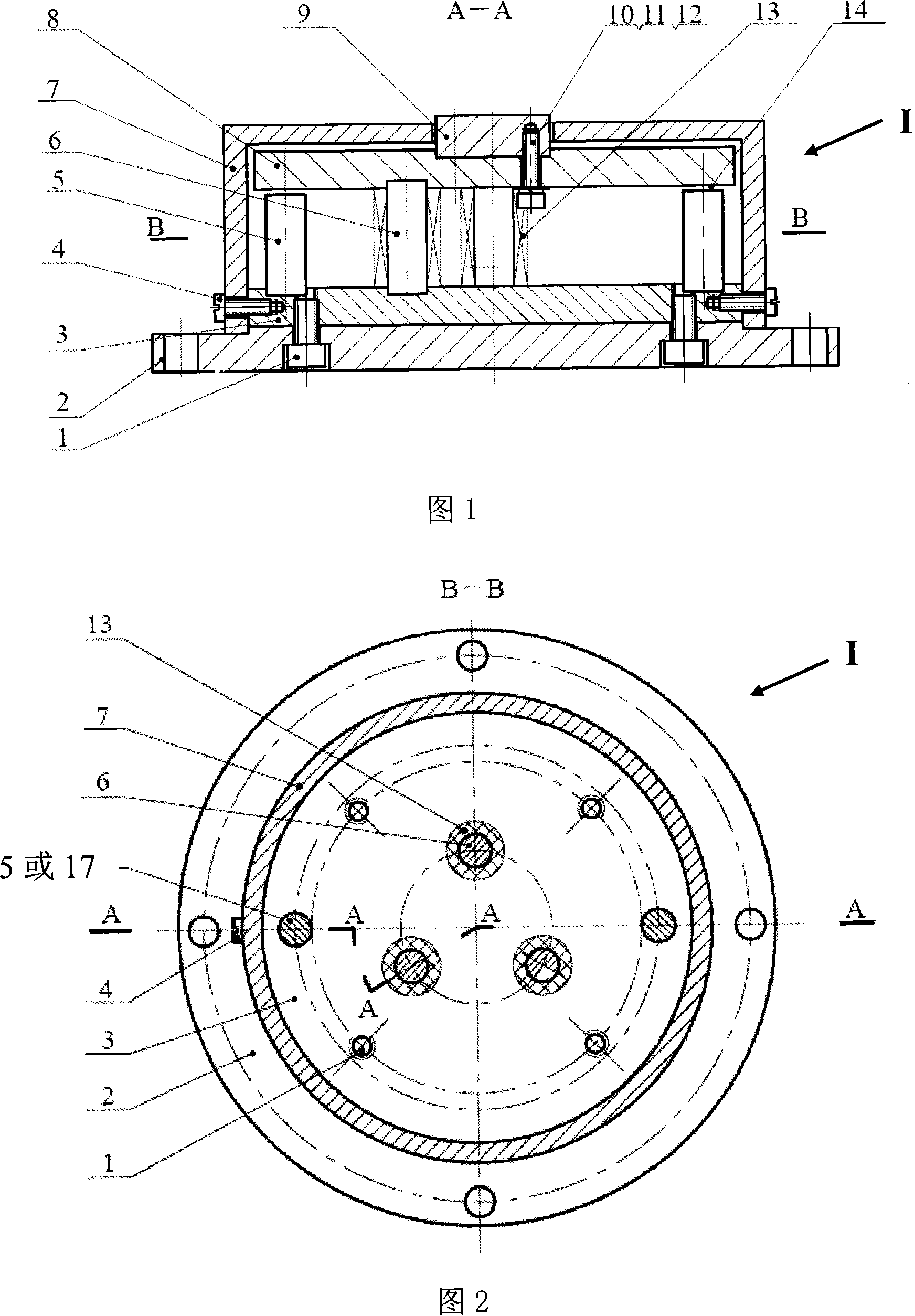
[0012] Further describe the present invention below in conjunction with embodiment and accompanying drawing thereof:

[0013] The embodiment of the giant magnetostrictive pressure sensor (hereinafter referred to as sensor) designed by the present invention (referring to Fig. 1, shown in 2), is characterized in that three giant magnetostrictive rods are vertically evenly distributed on the inner circle of the base 2 of the sensor 6. Two permanent magnet bars 5 or two excitation coils 17 are vertically and symmetrically arranged on the outer ring; the top and bottom of the two permanent magnet bars 5 or the two excitation coils 17 are respectively equipped with disk-shaped soft magnetic materials. The upper magnetic guide plate 8 and the lower magnetic guide plate 3 have a radius slightly larger than the installation radius of the permanent magnet rod 5 or the excitation coil 17; the magnetization directions of the two permanent magnet rods 5 are both axial and in the same direct...


PUM

PropertyMeasurementUnit
compressive strengthaaaaaaaaaa

Abstract

The invention relates to a giant magnctostrictivc material pressure sensor, which is characterized in that three giant magnctostrictivc material rods are vertically and evenly arranged on an inner circle of a sensor base and two permanent magnetic rods or two excitation windings are arranged vertically and systemically on three giant magnctostrictivc material rods; upper and lower disk magnetic inductive plates are respectively arranged on the above and at the bottom of the three giant magnctostrictivc material rods and the radiuses are a little bit bigger than the mounting radiuses of the permanent magnetic rods or the excitation windings; the magnetizing directions of the two permanent magnetic rods are axial and are the same; the two excitation windings have the same coiling direction and also the same current direction; the length of the permanent magnetic rods or the excitation windings is a little bit shorter than the length of the giant magnctostrictivc material rods to enable a gap between the top of permanent magnetic rods or the excitation windings and the bottom of the upper disk magnetic inductive plat; non-magnetic inductive glue is filled in the gaps to glue Hall units; inductive windings are coiled on the giant magnctostrictivc material rods; the upper disk magnetic inductive plate are arranged on a bearing block, the lower disk magnetic inductive plates are arranged on the base, an outer cover is arranged on the lower disk magnetic inductive plates, and encloses all parts on the base as a whole but the bearing block protrudes out of the upper surface of the outer cover.

Description

technical field [0001] The invention relates to pressure sensor technology, specifically a giant magnetostrictive pressure sensor, and the international patent classification number is proposed to be Int.C1.G01L 9 / 00 (2006.01) technical background [0002] Pressure sensors are widely used in industry. [0003] At present, the most widely used pressure sensors are resistive pressure sensors and piezoelectric pressure sensors. For resistive pressure sensors, the strain gauge must be pasted on the test piece or the elastic element of the sensor when testing the application. Therefore, the performance of the adhesive will directly affect the working characteristics of the strain gauge, which is prone to measurement errors. In addition, resistive pressure sensors are mainly used for the measurement of static force and low frequency dynamic force. Piezoelectric pressure sensors are mainly used for the measurement of dynamic force, because the measurement signal decays quickly wi...

Claims


Application Information

Patent Timeline
Patent Type & Authority Applications(China)
IPC IPC(8): G01L1/12G01L9/16
Inventor 杨庆新闫荣格樊长在张顺心童保林刘福贵夏煜周晓冬
Owner HEBEI UNIV OF TECH
Why Eureka
Try Eureka