Unmanned aerial vehicle base station deployment method for supplementing coverage by utilizing reflected beams

A technology of unmanned aerial vehicles and machine base stations, which is applied in wireless communication, radio transmission system, network planning, etc. It can solve the problems of not considering the coverage potential of reflected beams, unreasonable LOS link connection, etc., and achieve the effect of reducing the probability of interruption

Pending Publication Date: 2021-02-12
BEIJING UNIV OF POSTS & TELECOMM
View PDF0 Cites 7 Cited by
  • Summary
  • Abstract
  • Description
  • Claims
  • Application Information

AI Technical Summary

Problems solved by technology

[0005] Because drones can be deployed in the air and can achieve a high LOS probability, one analysis method assumes that the drone and the user must be connected through a direct link, but in a dense urban environment, due to the occlusion of buildings, There is a large part of the area on the ground that cannot be covered by the UAV LOS link, so it is unreasonable to directly assume that the UAV and the user can be connected through the LOS link; another analysis method takes into account the blocking effect of the building, if A blocked direct link is considered a user outage, an assumption that does not take into account the coverage potential of reflected beams

Method used


Image

  • Unmanned aerial vehicle base station deployment method for supplementing coverage by utilizing reflected beams
  • Unmanned aerial vehicle base station deployment method for supplementing coverage by utilizing reflected beams
  • Unmanned aerial vehicle base station deployment method for supplementing coverage by utilizing reflected beams

Examples


Embodiment Construction

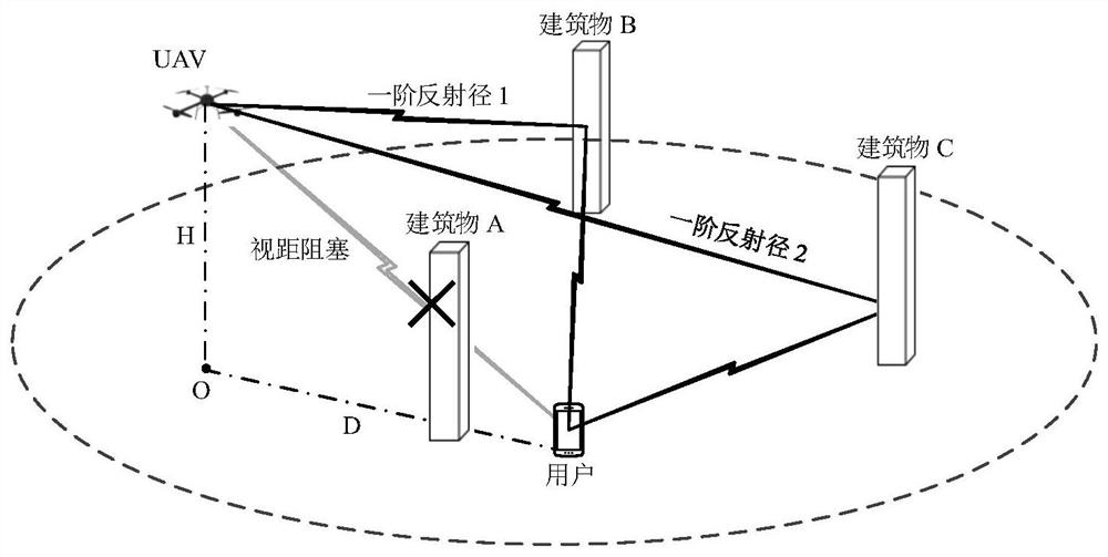
[0044] Aiming at the coverage blind area of ​​the direct beam of the UAV cellular network, the present invention proposes a UAV base station deployment method using reflected beam supplementary coverage. In dense urban areas, buildings cause serious blockage to millimeter wave beams. For example, the attached figure 1 As shown, the direct beam from the drone to the user is blocked, causing the user to be in the coverage blind spot of the direct beam of the drone. Comes the cost increase, however, the building blocks the beam while generating abundant reflections, as shown in the attached figure 1 The first-order reflection path 1 and the first-order reflection path 2 in are just aligned with the user and can provide services for the user. At this time, it involves the selection of the first-order reflection path. We assume that the UAV chooses the first-order reflection path with the shortest path length Provide services to users.

[0045] Consider using the reflected beam t...


PUM


Abstract

The invention provides an unmanned aerial vehicle base station deployment method for supplementing coverage by using reflected beams. Specifically, when the direct beam between the unmanned aerial vehicle and the user is not blocked, the direct beam is used for coverage, and when the direct beam is blocked, the reflected beam is used for coverage supplement, so that the coverage potential of the reflected beam is exerted, the coverage area of the unmanned aerial vehicle is expanded, and the outage probability of the user is effectively reduced. The method comprises the following steps: modeling and analyzing the influence of a building on millimeter wave propagation of the unmanned aerial vehicle, selecting a first-order reflection path with the shortest path length for service, deriving aprobability density expression of a vertical projection length s serving a first-order reflection beam, and finally obtaining the coverage rate of an unmanned aerial vehicle base station; substituting the actual propagation environment parameters of the target coverage area, such as the density and the average height of the building, into the coverage rate expression, obtaining the unmanned aerial vehicle deployment height and density with the optimal coverage performance according to the change relationship of the coverage rate with the unmanned aerial vehicle deployment parameters, and providing guidance for the deployment of an actual unmanned aerial vehicle base station.

Description

technical field [0001] The present invention relates to the technical field of wireless communication, and in particular to the design of a deployment method of an unmanned aerial vehicle (UAV) base station network. Background technique [0002] Future networks will face the huge challenge of users' high coverage and high capacity requirements. In the existing terrestrial cellular network, the deployment cycle of ground base stations is long and the cost is high, making it difficult to meet the service requirements of high dynamic scenarios. With significant advancements in UAV (Unmannedaerial vehicle, UAV) technology, such as better power management techniques, increased payload capacity, longer flight duration, etc., UAVs can be used for a variety of purposes, such as filming , surveillance, transportation, communication, etc. In terms of communication, due to the high dynamic characteristics of drones and the line-of-sight transmission link between drones and ground use...

Claims


Application Information

Patent Timeline
Patent Type & Authority Applications(China)
IPC IPC(8): H04W16/18H04L12/24H04B7/185
CPCH04B7/18506H04L41/145H04W16/18
Inventor 张鸿涛赵嘉怡陈子仪杨丽云
Owner BEIJING UNIV OF POSTS & TELECOMM
Why Eureka
Try Eureka