Power battery mounting structure and vehicle

A technology of power battery and installation structure, applied in the direction of power unit, electric power unit, superstructure, etc., can solve the problems of high reliability, insufficient structural strength, insufficient depth of tire pool, etc. The effect of reducing development time

Pending Publication Date: 2021-02-19
CHONGQING CHANGAN AUTOMOBILE CO LTD
View PDF14 Cites 0 Cited by
  • Summary
  • Abstract
  • Description
  • Claims
  • Application Information

AI Technical Summary

Problems solved by technology

[0005] The purpose of the present invention is to provide a power battery installation structure and a vehicle, which can solve the problem that the power battery cannot be installed due to insufficient spare tire pool depth or insufficient structural strength, with high reliability and low cost

Method used


Image

  • Power battery mounting structure and vehicle
  • Power battery mounting structure and vehicle
  • Power battery mounting structure and vehicle

Examples


Embodiment Construction

[0021] The present invention will be described in detail below in conjunction with the accompanying drawings.

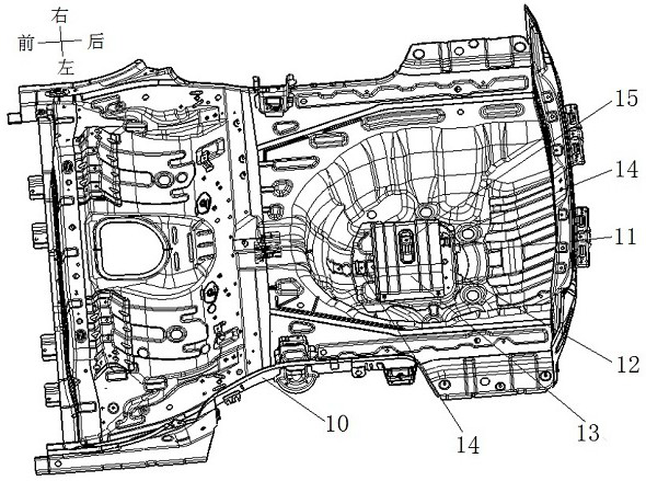
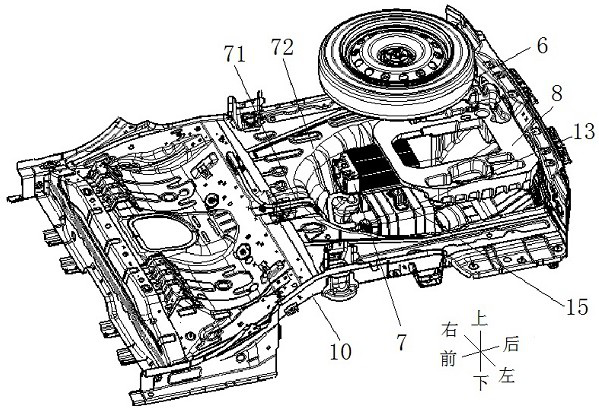
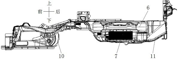
[0022] see Figure 4 and Figure 5 , the power battery installation structure shown includes a rear floor 1 and an installation box 2, the rear section of the rear floor 1 is recessed downwards to form a spare tire pool 11, the installation box 2 is fixed below the spare tire pool 11, and the installation box 2 There is an accommodation cavity inside, and an opening 21 communicating with the accommodation cavity is provided at the top. The opening 21 is provided with an overlapping flange 22 welded and fixed to the lower surface of the spare tire pool 11, in order to ensure the sealing of the accommodation cavity and prevent the outside Foreign matter enters, apply sealant 9 at the overlap between the installation box 2 and the spare tire pool 11, apply welding sealant on the inside of the overlap close to the accommodation cavity for sealing, and apply a coating on...


PUM


Abstract

The invention discloses a power battery mounting structure. The structure comprises a rear floor and a mounting box, wherein the rear section of the rear floor is sunken downwards to form a spare tirepool, the mounting box is fixed below the spare tire pool, a containing cavity is formed in the mounting box, an opening communicated with the containing cavity is formed in the top end of the mounting box, and a lap joint flange fixedly connected with the lower surface of the spare tire pool is arranged at the opening; a through hole is formed in the position, corresponding to the opening, of the spare tire pool. The structure is advantaged in that a problem that the power battery cannot be installed due to insufficient depth or insufficient structural strength of the spare tire pool can besolved, reliability is high, and cost is low. The utility model further discloses a vehicle which comprises a rear floor assembly, and the rear floor assembly comprises the power battery mounting structure.

Description

technical field [0001] The invention relates to a vehicle body component, in particular to a power battery installation structure and a vehicle. Background technique [0002] see figure 1 , the shown existing installation structure for assembling power batteries includes an existing rear floor 10, a battery mounting plate 12 and a spare tire mounting bracket 13, and the rear section of the existing rear floor 10 is recessed downward to form a spare tire pool 11 , the battery mounting plate 12 is fixed on the bottom of the spare tire pool 11, and the battery mounting plate 12 is provided with a plurality of clamping brackets 14 corresponding to the clamping slots on the power battery 7, specifically, the power battery 7 It is a 48V lithium battery. The spare tire mounting bracket 13 is in an inverted U shape, and the lower end leg is fixedly connected to the battery mounting plate 12. The spare tire mounting bracket 13 and the battery mounting plate 12 are enclosed to form ...

Claims


Application Information

Patent Timeline
Patent Type & Authority Applications(China)
IPC IPC(8): B60K1/04B62D25/20B62D43/06
CPCB60K1/04B62D25/20B62D43/06
Inventor 伍谦魏建谭勇
Owner CHONGQING CHANGAN AUTOMOBILE CO LTD
Why Eureka
Try Eureka