Ultrahigh-pressure sand control fracturing valve

A fracturing valve, ultra-high pressure technology, applied in the field of fracturing valves, can solve the problems of reducing the service life of fracturing valves, valve plate wear, fracturing valve stuck, etc., to reduce the operating torque of the valve stem, improve service life, Avoid stuck effects

Active Publication Date: 2021-02-19
CHINA UNIV OF PETROLEUM (EAST CHINA)
View PDF7 Cites 1 Cited by
  • Summary
  • Abstract
  • Description
  • Claims
  • Application Information

AI Technical Summary

Problems solved by technology

However, ultra-high pressure conditions are easy to occur during the fracturing process. The existing fracturing valves often fail to safely release the ultra-high pressure, which increases the operating torque of the valve stem and makes it difficult to open and close the large valve core; at the same time, the undischarged Ultra-high pressure will directly act on the large valve core to cause the vibration of the large valve core. There are two main problems in the vibration of the large valve core. On the one hand, it will increase the wear of the sealing surface between the valve plate and the sealing valve seat, especially the large valve core. When it is close to the opening and closing positions, the sealing surface wears more seriously due to the large pressure difference, and the long-term wear will significantly reduce the service life of the fracturing valve; on the other hand, it will generate torque to twist the valve stem. If the torque If it is too large, it will directly cause damage to the large spool
[0003] In addition, due to the fracturing sand contained in the fracturing fluid, the fracturing sand will enter the valve body during the fracturing process, which will cause the fracturing valve to be stuck to varying degrees, the switch is not in place, the seal leaks, and the valve plate is worn.

Method used


Image

  • Ultrahigh-pressure sand control fracturing valve
  • Ultrahigh-pressure sand control fracturing valve
  • Ultrahigh-pressure sand control fracturing valve

Examples


Embodiment Construction

[0026] In order to make the purpose, technical solutions and advantages of the present invention clearer, the present invention will be further described in detail below in conjunction with the accompanying drawings. Obviously, the described embodiments are only some of the embodiments of the present invention, rather than all of them. Based on the embodiments of the present invention, all other embodiments obtained by persons of ordinary skill in the art without making creative efforts belong to the protection scope of the present invention.

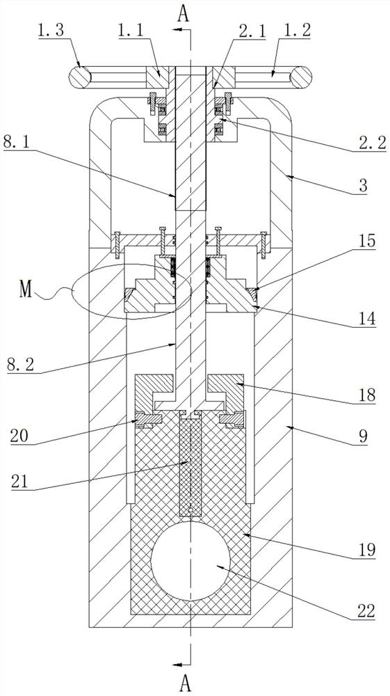
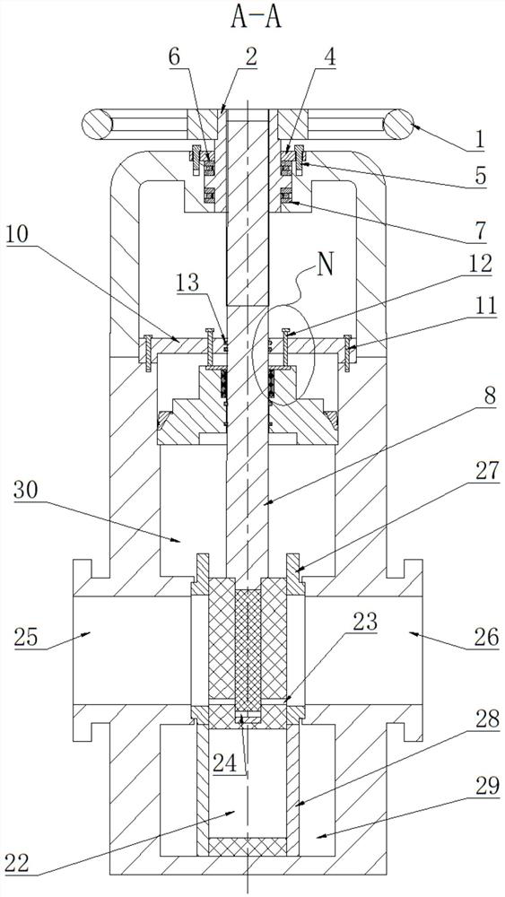
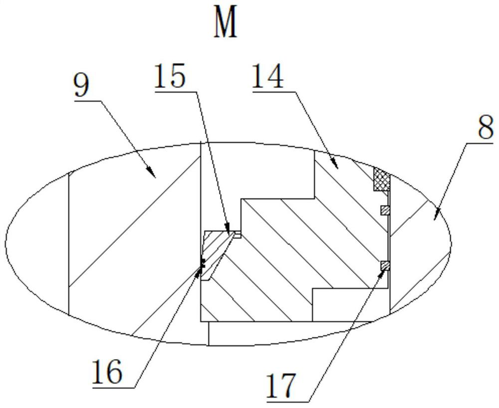
[0027] The following will combine Figure 1 to Figure 10 An ultra-high pressure sand control fracturing valve according to an embodiment of the present invention will be described in detail.

[0028] refer to figure 1 , figure 2 , image 3 , Figure 4 , Figure 6As shown, the embodiment of the present invention provides an ultra-high pressure sand control fracturing valve, including a valve body 9, a valve stem 8 installed in the ...


PUM


Abstract

The invention relates to a fracturing valve, in particular to an ultrahigh-pressure sand control fracturing valve, and belongs to the technical field of fracturing. The valve comprises a valve body, avalve rod installed in the valve body and a valve plate connected with the valve rod, and is characterized in that the valve plate is of a combined structure and comprises an opening and closing valve plate and a pressure relief valve plate, and the pressure relief valve plate is installed in a pressure relief valve plate containing cavity formed in the upper portion of the opening and closing valve plate in a sliding mode. The valve rod drives the pressure release valve plate to annularly slide between the valve plate hook and the opening and closing valve plate, when the valve rod slides tothe upper limit position relative to the valve plate hook, the pressure release hole of the pressure release valve plate is coaxial with the pressure release hole of the opening and closing valve plate, the fracturing valve is delayed to open for pilot pressure release, and the valve plate is located between the two valve plate seats. After the fracturing valve conducts pressure relief, the valverod drives the valve plate to move upwards to open the fracturing valve. The fracturing valve has the beneficial effects that the fracturing valve can be suitable for ultrahigh-pressure fracturing working conditions, fracturing sand can be effectively prevented from entering the valve cavity, and internal components of the valve cavity are protected against damage.

Description

technical field [0001] The invention relates to a fracturing valve, in particular to an ultra-high pressure sand control fracturing valve, which belongs to the technical field of fracturing. Background technique [0002] The fracturing valve is an indispensable equipment for the fracturing step in the process of oil exploitation. The existing fracturing valve has only one main cut-off large spool in the valve body. When the gate valve is opened and closed, the actuator drives the large spool to move up and down through the valve stem. Realize the opening and closing task. However, ultra-high pressure conditions are likely to occur during the fracturing process. The existing fracturing valves often fail to safely release the ultra-high pressure, which increases the operating torque of the valve stem and makes it difficult to open and close the large valve core; at the same time, the undischarged Ultra-high pressure will directly act on the large valve core to cause the vibra...

Claims


Application Information

Patent Timeline
Patent Type & Authority Applications(China)
IPC IPC(8): E21B43/26E21B34/14E21B34/08E21B41/00
CPCE21B43/26E21B34/14E21B34/08E21B41/00
Inventor 张辛樊燊王旱祥杨亚东高嘉宝王进裴安平刘延鑫董祥伟
Owner CHINA UNIV OF PETROLEUM (EAST CHINA)
Why Eureka
Try Eureka