
Slag discharging and water draining device for gas pipeline

A water discharger and pipeline technology, used in gas discharge, safety devices, mining equipment, etc., can solve problems such as easy adhesion, accumulation at the bottom of the slag discharger, difficult discharge of coal slag and sludge, affecting the use of the slag discharger, etc.

Inactive Publication Date: 2021-02-19
刘军
View PDF0 Cites 0 Cited by
  • Summary
  • Abstract
  • Description
  • Claims
  • Application Information

AI Technical Summary

Problems solved by technology

[0003] However, the water discharge system will only be opened after the water level rises to a certain height, which makes the water at the bottom of the slag discharge device relatively stable, and the cinders and silt in the water are easy to adhere and accumulate at the bottom of the slag discharge device. , Compared with the overall size of the slag discharge drain, the drainage pipe opening is smaller, which makes it difficult to discharge the cinder and sludge in the slag discharge drain. After long-term use, it is easy to block, which affects the subsequent use of the slag discharge drain.

Method used


Image

  • Slag discharging and water draining device for gas pipeline
  • Slag discharging and water draining device for gas pipeline
  • Slag discharging and water draining device for gas pipeline

Examples


Embodiment Construction

[0017] The following will clearly and completely describe the technical solutions in the embodiments of the present invention with reference to the accompanying drawings in the embodiments of the present invention. Obviously, the described embodiments are only some, not all, embodiments of the present invention. Based on the embodiments of the present invention, all other embodiments obtained by persons of ordinary skill in the art without making creative efforts belong to the protection scope of the present invention.

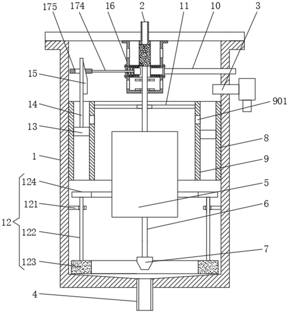
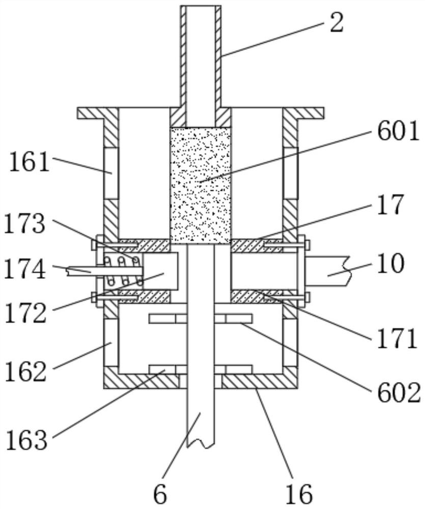
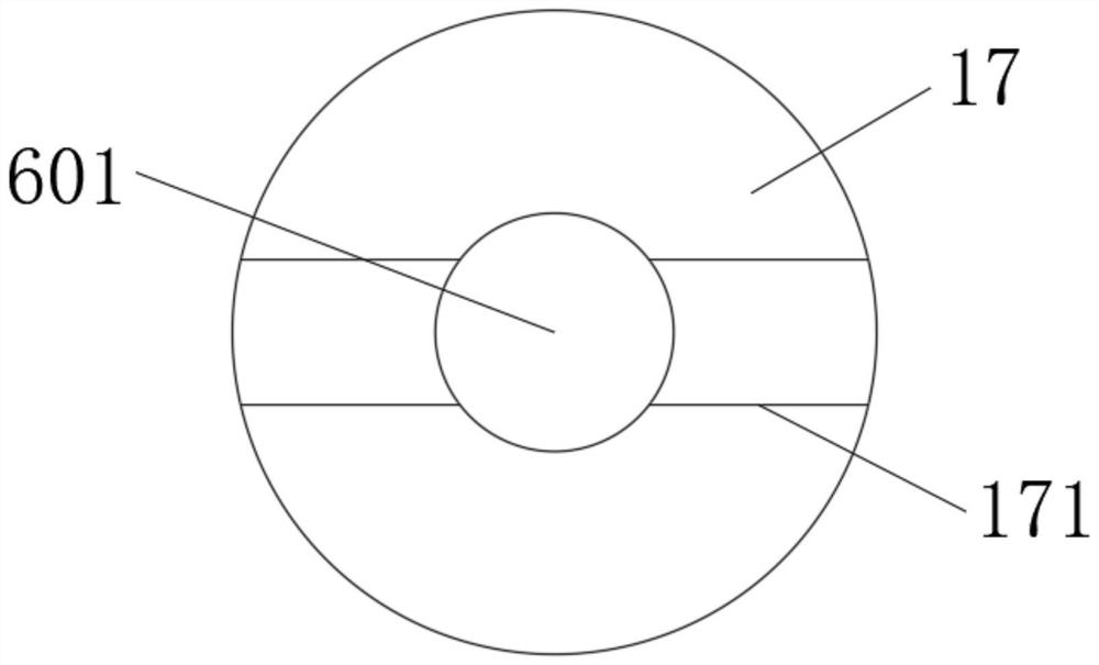
[0018] see Figure 1-4 , a slag discharge water release device for gas pipelines, comprising a tank body 1, a negative pressure balance pipe 2, a water inlet pipe 3, a drain pipe 4, a floating block 5, a linkage rod 6, an air guide pipe 10, and the top of the tank body 1 is sealed A cover plate is connected, and the middle part of the cover plate is provided with a negative pressure balance pipe 2 extending to the inside of the tank body 1. The top of the nega...


PUM


Abstract

The invention relates to the field of gas exploitation equipment, and discloses a slag discharging and water draining device for a gas pipeline. The slag discharging and water draining device comprises a tank body, a negative pressure balance pipe, a water inlet pipe, a water draining pipe, a floating block, a linkage rod and a gas guide pipe, wherein a sealed cover plate is arranged at the top ofthe tank body, the negative pressure balance pipe is arranged in the middle of the cover plate, the top end of the negative pressure balance pipe communicates with a gas extraction pipeline, the water inlet pipe is fixedly arranged at the top of the side surface of the tank body in a sleeving mode, and one end of the water inlet pipe communicates with the gas extraction pipeline. According to theslag discharging and water draining device for the gas pipeline, through the structural design of an annular water storage chamber in the tank body, in the water inlet stage, the annular water storage chamber stores water firstly, in the water draining stage, the water stored in the annular water storage chamber flows down finally, so that before each time of water draining is finished, the gravitational potential energy of the water in the annular water storage chamber is used for providing kinetic energy, impurities such as coal slag and sludge which are adhered to the bottom of the tank body are washed away, and then the problem that the coal slag and the sludge are deposited and accumulated in the slag discharging and water draining device to cause blockage is solved.

Description

technical field [0001] The invention relates to the field of gas mining equipment, in particular to a slag discharger for gas pipelines. Background technique [0002] In the gas drainage pipeline, the slag discharge device is an indispensable automatic water discharge device for the coal mine gas drainage system. It is suitable for automatic water discharge of the main pipe, main pipe, and branch pipe of the gas drainage and utilization system. Both the water inlet pipe and the negative pressure balance pipe are connected to the gas pipeline. Under the negative pressure of the gas pipeline, the drain valve is closed. After the water level reaches a certain height, the float moves up to trigger the action, and the water drain valve opens. Negative pressure balance tubes are all closed. [0003] However, the water discharge system will only be opened after the water level rises to a certain height, which makes the water at the bottom of the slag discharge device relatively st...

Claims


Application Information

Patent Timeline
IPC IPC(8): E21F7/00
CPCE21F7/00
Inventor 刘军
Owner 刘军
Learn More