
Oil tank reinforced vibration test device and method

A technology of vibration test and oil tank, which is applied in vibration test, measuring device, machine/structural component test, etc., can solve the problems of life reduction, complex structure, deformation of oil tank structure, etc., and achieve reasonable design, convenient operation and application, and overall The effect of simple structure

Pending Publication Date: 2021-02-19
盐城市顺发油箱有限公司
View PDF10 Cites 1 Cited by
  • Summary
  • Abstract
  • Description
  • Claims
  • Application Information

AI Technical Summary

Problems solved by technology

[0002] The fuel tank is a special container for storing fuel and hydraulic oil in various fuel machinery such as automobiles and tractors. The fuel carrier is prone to vibration during driving and causes resonance in the iron fuel tank, which causes structural deformation and dynamic stress of the fuel tank, resulting in reduced service life.
The vibration test device in the prior art adopts the vibration drive of swaying around the shaft and loads the fuel tank with a fixture. Not only is the structure complex and the clamping is cumbersome, but also when the fuel tanks have different shapes, the positioning and vibration of the empty fuel tank are not reliable. The force in the tank during the process has not been considered, and the resonance effect is not obvious due to shaking only, and the clamping force point is easy to damage the fuel tank during the vibration process. Therefore, it is urgent to develop a simple and easy-to-operate enhanced vibration test device and Test method to simulate the use environment of the fuel tank, conduct vibration transmission to detect the vibration fatigue strength of the fuel tank, to detect and control the quality of the fuel tank, and provide a basic guarantee for the development and application of the fuel tank

Method used


Image

  • Oil tank reinforced vibration test device and method
  • Oil tank reinforced vibration test device and method
  • Oil tank reinforced vibration test device and method

Examples


Embodiment Construction

[0018] The specific embodiments of the present invention will be further described below in conjunction with the accompanying drawings.

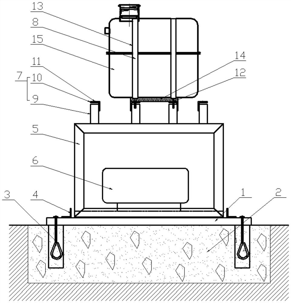
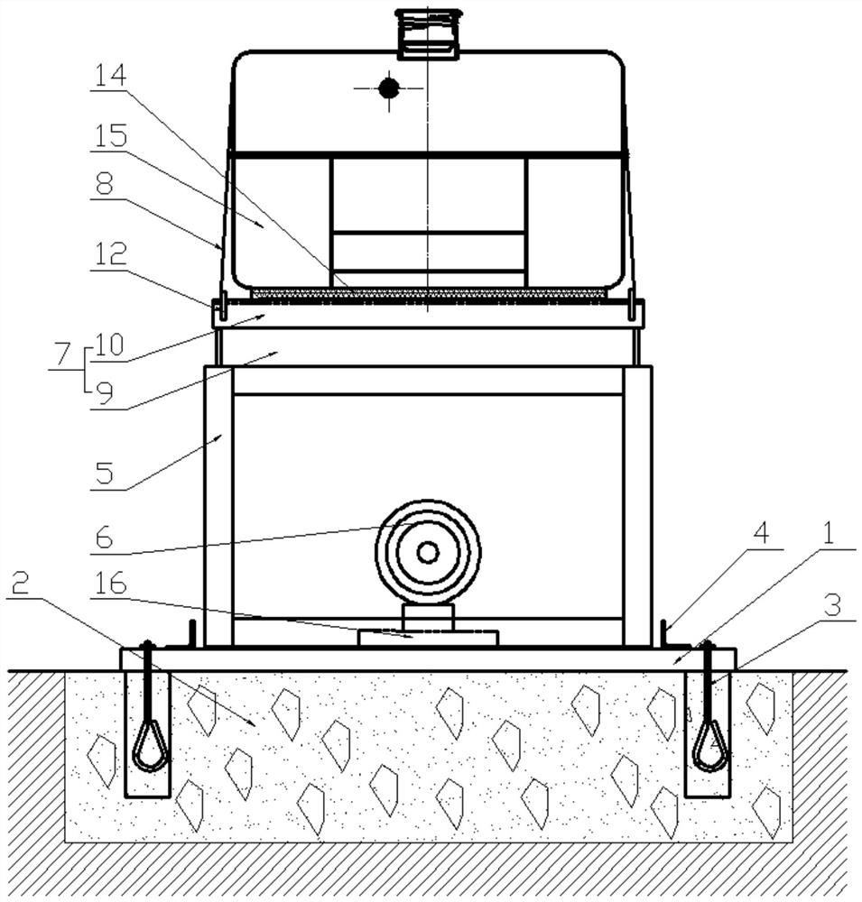
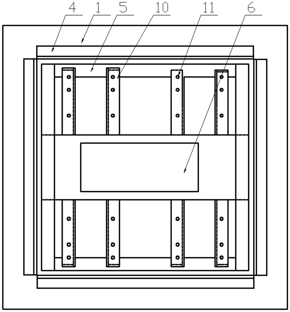
[0019] A fuel tank strengthened vibration test device, comprising a fixed vibration frame platform 1, the bottom of the vibration frame platform 1 platform is a foundation 2, and a number of positioning bolts 3 fixed to the foundation 2 are arranged on the vibration frame platform 1, wherein the vibration The frame platform 1 is provided with a baffle assembly and a frame 5 that vibrates strongly inside the baffle assembly, and the baffle assembly includes a baffle 4 located around the frame 5, fixed with the baffle assembly, and having an L-shaped cross-section;

[0020] The inside of the frame 5 is provided with a powerful vibrator 6, the powerful vibrator 6 is an attached plate vibrator B-30 model, the bottom of the powerful vibrator 6 and the bottom of the frame 5 are provided with a vibrator fixing plate 16, the The top of the frame 5 i...


PUM


Abstract

The invention relates to an oil tank reinforced vibration test device and method. The oil tank reinforced vibration test device comprises a fixed vibration frame platform, which is provided with a baffle plate assembly and a frame located in the baffle plate assembly and used for strong vibration, the frame is internally provided with a strong vibrator, and a plurality of fixing frames at the topof the frame are provided with oil tank binding belts which are arranged outside an oil tank and fixedly connected. During a vibration test, water is injected into an oil tank until the volume of thewater accounts for 80% of the volume of the oil tank, then an oil tank cover is screwed up, a strong vibrator is started, and is stopped every 5 min, and the cracking condition of the oil tank is observed and recorded. According to the invention, through the frame vibrating on the vibration frame platform, the oil tank binding belts bind the oil tank to transmit vibration to the oil tank to form resonance, water is injected to carry out an enhanced vibration test, an enhanced vibration test result is judged according to the vibration cracking condition of the oil tank within a period, and theapplication environment of the oil tank on a fuel machine is fully simulated, so that the vibration fatigue strength of the oil tank is effectively detected, and the quality of the oil tank is effectively controlled.

Description

technical field [0001] The invention relates to a fuel tank enhanced vibration test device and a test method, belonging to the technical field of fuel tank detection equipment. Background technique [0002] The fuel tank is a special container for storing fuel oil and hydraulic oil for various fuel machinery such as automobiles and tractors. The fuel carrier is prone to vibration during driving and causes resonance in the iron fuel tank, which causes structural deformation and dynamic stress of the fuel tank, resulting in reduced service life. The vibration test device in the prior art adopts the vibration drive of swaying around the shaft and loads the fuel tank with a fixture. Not only is the structure complex and the clamping is cumbersome, but also when the fuel tanks have different shapes, the positioning and vibration of the empty fuel tank are not reliable. The force in the tank during the process has not been considered, and the resonance effect is not obvious due to...

Claims


Application Information

Patent Timeline
Patent Type & Authority Applications(China)
IPC IPC(8): G01M7/02
CPCG01M7/027G01M7/02
Inventor 成浩成玉顺
Owner 盐城市顺发油箱有限公司
Learn More