Water-cooled fuel gas sampling rake

A water-cooled, gas-fired technology, applied in sampling, sampling devices, measuring devices, etc., can solve problems affecting accuracy, affecting the original structure of the flow field, and high demand for fine control, so as to prevent deviation and improve heat transfer efficiency , the effect of improving accuracy

Active Publication Date: 2021-02-19
TONGJI UNIV
View PDF19 Cites 1 Cited by
  • Summary
  • Abstract
  • Description
  • Claims
  • Application Information

AI Technical Summary

Problems solved by technology

[0003] Since the temperature, pressure, and flow rate of the flue gas composition measurement environment are much lower than the internal flow field of the combustion chamber, the following issues need to be paid attention to when sampling the flue gas composition: first, ensure that the combustion chemical reaction in the flue gas entering the sampling equipment The rapid termination can accurately reflect the real sample gas composition of the sampling point; secondly, the parameters such as temperature and velocity in the flow field in the combustion chamber are much higher than those at the outlet, and the sampling equipment faces serious risk of ablation, so the sampling equipment needs to be protected
[0005] However, in the low-pollution combustion technology, there is a high demand for the fine control of the flow field shape in the combustion chamber and the chemical reaction process in it. Unlike traditional combustion equipment, the flow field in the combustion chamber of a gas turbine has strong characteristics. Among them, the appearance of the sampling section of the flue gas sampling equipment in the flow field is mostly cylindrical or cuboid. During the sampling process, the sampling equipment will affect the original structure of the flow field, interfere with the reaction process in the combustion chamber, and affect the accuracy of subsequent experimental measurements. , and the cooling effect of the sampling rake still needs to be improved

Method used


Image

  • Water-cooled fuel gas sampling rake
  • Water-cooled fuel gas sampling rake
  • Water-cooled fuel gas sampling rake

Examples


Embodiment 1

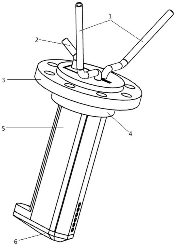
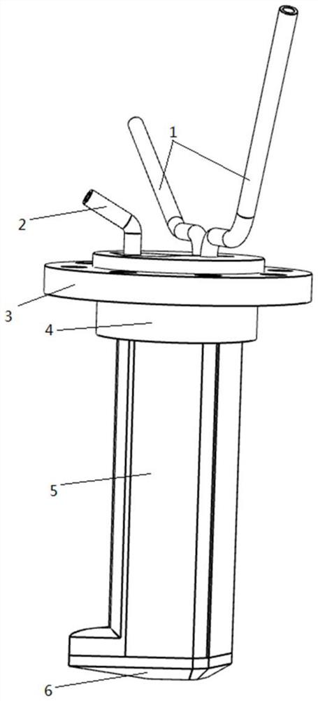
[0036] A water-cooled gas sampling rake, the overall structure is as follows figure 1 and figure 2 As shown, it includes: sampling section, cooling pipeline 1, sample gas pipeline 2, and mounting flange 3. The cooling pipeline 1 and the sample gas pipeline 2 are connected to the sampling section. The coolant enters the sampling section through the cooling pipeline 1. The collected high-temperature flue gas is transmitted to the flue gas analysis equipment through the sample gas pipeline 2. The mounting flange 3 is fixed on the sampling section. On the section, a sampling hole 54 is provided on the sampling section, and the sampling section includes: a mixing section 4 , a measuring section 5 , and a wedge-shaped bottom 6 .

[0037] Specifically, the bottom of the measuring section 5 is integrally formed with the wedge-shaped bottom 6 .

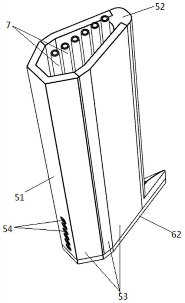
[0038] Such as image 3 As shown, the measurement section 5 is a hollow prism structure, including a windward surface 51, a leeward surfa...


PUM

PropertyMeasurementUnit
diameteraaaaaaaaaa
heightaaaaaaaaaa

Abstract

The invention relates to a water-cooled fuel gas sampling rake, which is used for directly measuring high-temperature and high-pressure internal flow field fuel gas, and is characterized in that the sampling section of the sampling rake comprises a measuring section and a wedge-shaped bottom, the measuring rake is of a hollow prism structure, the cross section is approximately wedge-shaped, and acooling pipeline and a plurality of sampling pipes are arranged in the measuring section. According to the invention, compared with a cylindrical sampling section, the geometric structure of the sampling rake is wedge-shaped, so that the damage to the rear structure of a flow field is relatively small; the multiple sampling pipes can avoid interference of abnormal points; high-temperature flue gasin the sampling pipes can be rapidly cooled through the cooling pipeline; and the heat exchange efficiency is improved by means of the protruding blocks on the inner wall of the measuring section andthe threads on the pipe walls of the sampling pipes, and overheating protection is conducted on the wall face of the sampling rake.

Description

technical field [0001] The invention relates to the field of gas sampling, in particular to a water-cooled gas sampling rake. Background technique [0002] The combustor is one of the three core components of a gas turbine. Its function is to convert the chemical energy of the fuel into thermal energy to drive the high-speed rotation of the turbine, and then convert it into mechanical work. In the combustion state, the interior of the combustion chamber flame tube is high-temperature, high-pressure, and high-speed multi-phase turbulent combustion, and its combustion effect can usually be obtained by analyzing the composition of the reaction products. As the country's requirements for pollutant emission concentration become increasingly stringent, it is necessary to accurately measure the composition of the gas at the outlet of the combustion chamber. The existing flue gas sampling equipment is mostly used to measure the composition of the flue gas at the outlet. [0003] Si...

Claims


Application Information

Patent Timeline
Patent Type & Authority Applications(China)
IPC IPC(8): G01N1/22
CPCG01N1/2247G01N1/2252
Inventor 程嘉颖宗超朱彤
Owner TONGJI UNIV
Why Eureka
Try Eureka