Spray cooling device of solid waste incineration system

A spray cooling, solid waste technology, applied in gaseous discharge wastewater treatment, water/sludge/sewage treatment, steam condensation, etc., can solve the problems of environmental pollution, high cost, waste of raw materials, etc.

Pending Publication Date: 2021-02-23
徐新会
View PDF0 Cites 1 Cited by
  • Summary
  • Abstract
  • Description
  • Claims
  • Application Information

AI Technical Summary

Problems solved by technology

[0004] In order to overcome the shortcomings of the traditional incineration method, which directly discharges the waste gas into the water, and then discharges it, the cost is high, it is easy to waste raw materials, and pollute the environment. The technical problem to be solved is: to provide a low-cost, low-cost, Spray cooling device for solid waste incineration system for treating and purifying waste gas

Method used


Image

  • Spray cooling device of solid waste incineration system
  • Spray cooling device of solid waste incineration system
  • Spray cooling device of solid waste incineration system

Examples


Embodiment 1

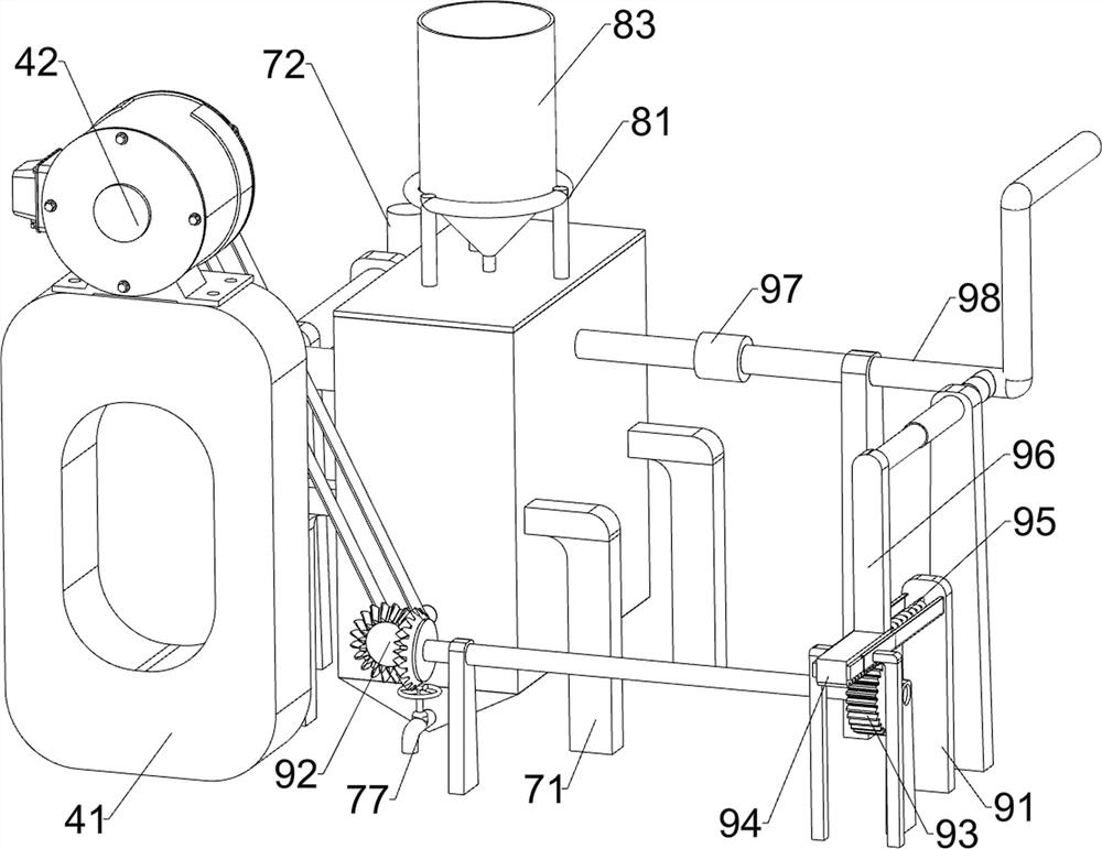
[0053] A spray cooling device for solid waste incineration system, such as figure 1 As shown, it includes a base 1, a water storage tank 2, a spray cooling mechanism 3 and an air extraction mechanism 4. The water storage tank 2 is arranged on the right rear side of the top of the base 1, and the spray cooling mechanism 3 is connected to the left rear side of the top of the base 1. 1. An air extraction mechanism 4 is connected to the left front side of the top.

[0054] The staff can connect the exhaust gas discharge pipe to the spray cooling mechanism 3, and then start the spray cooling mechanism 3, the exhaust gas is liquefied through the spray cooling mechanism 3, and the spray cooling mechanism 3 works to drive the exhaust mechanism 4 to work, and the remaining gas It can be discharged through the exhaust mechanism 4, so that the waste gas can be processed. After the treatment is completed, stop the work of the spray cooling mechanism 3 and get final product.

Embodiment 2

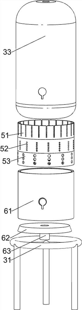
[0056] On the basis of Example 1, such as figure 2 As shown, the spray cooling mechanism 3 includes a support seat 31, an air intake pipe 32, a cooling tank 33, a water pump 34, a water inlet pipe 35 and an atomized water nozzle 36, and the left rear side of the base 1 is connected with a support seat 31, and the support seat The upper part of 31 is provided with a cooling tank 33, the top of the cooling tank 33 is connected with an air intake pipe 32, the top of the base 1 is provided with a water pump 34, the water pump 34 is connected with the water storage tank 2, the water pump 34 is located on the right side of the cooling tank 33, and the water pump 34 Both front and rear sides of the upper part are connected with water inlet pipes 35, and the upper parts of the water inlet pipes 35 are connected with atomized water nozzles 36, and the atomized water nozzles 36 are connected with the cooling tank 33 tops.

[0057] The exhaust mechanism 4 includes a mounting seat 41, a ...

Embodiment 3

[0060] On the basis of Example 2, such as Figure 3 to Figure 7 As shown, it also includes an exhaust gas pretreatment mechanism 5. The exhaust gas pretreatment mechanism 5 includes a first filter box 51, a second filter box 52 and a third filter box 53. The upper part of the inner wall of the cooling tank 33 is connected with the first A filter box 51 , a second filter box 52 and a third filter box 53 .

[0061] Also includes a gas-liquid separation mechanism 6, the gas-liquid separation mechanism 6 includes a diversion pipe 61, a diverter plate 62 and a water outlet pipe 63, the lower part of the inner wall of the cooling tank 33 is connected with a diversion pipe 61, and the bottom of the inner wall of the cooling tank 33 is connected with a water outlet pipe 63 , the top of the outlet pipe 63 is connected with a diverter plate 62 , and the diverter plate 62 is located below the flow guide pipe 61 .

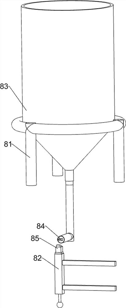
[0062] Also include sewage filter mechanism 7, sewage filter mechanism 7...


PUM


Abstract

The invention relates to a spray cooling device, in particular to a spray cooling device of a solid waste incineration system. The spray cooling device of the solid waste incineration system is capable of recycling water and liquid, low in cost and capable of treating and purifying waste gas. The spray cooling device of the solid waste incineration system comprises a base, a spraying cooling mechanism and an air extracting mechanism, and a water storage tank is arranged on one side of the top of the base; one side of the top of the base is connected with the spraying cooling mechanism; and oneside of the top of the base is connected with the air extracting mechanism. Through cooperation of the spraying cooling mechanism and the air extracting mechanism, the waste gas is cooled and liquefied, then an air exhaust fan is driven to rotate, and residual gas is exhausted; and by arranging a waste gas pretreatment mechanism, the liquefied waste gas is primarily filtered.

Description

technical field [0001] The invention relates to a spray cooling device, in particular to a spray cooling device for a solid waste incineration system. Background technique [0002] Garbage is mostly waste items that lose their use value and cannot be used. They are an important link in the material cycle, and they are solid and fluid substances that are not needed or useless. [0003] Garbage incinerators generally use pulverized coal to burn these solid wastes, and the waste gas discharged from the combustion is directly discharged into the sky through a very high exhaust port, or the waste gas is directly poured with tap water, so that the waste gas enters the water and becomes waste water, because the purification cost is relatively high , Most manufacturers will choose to directly discharge the waste water. This method also pollutes the environment on the basis of wasting raw materials. Contents of the invention [0004] In order to overcome the shortcomings of the tr...

Claims


Application Information

Patent Timeline
Patent Type & Authority Applications(China)
IPC IPC(8): B01D53/00B01D5/00C02F9/04C02F103/18
CPCB01D5/0027B01D5/0087B01D5/009B01D53/002C02F1/001C02F1/5281C02F2103/18
Inventor 徐新会
Owner 徐新会
Why Eureka
Try Eureka