
Adsorption material circulating moving type adsorption device for tail gas treatment

An adsorption material and tail gas treatment technology, applied in gas treatment, membrane technology, dispersed particle separation, etc., can solve the problems of insufficient adsorption of adsorption materials, large capital consumption, pollution, etc., and achieve high utilization rate of desorption steam and save steam The effect of high dosage and high desorption efficiency

Pending Publication Date: 2021-02-23
石伟东 +1
View PDF0 Cites 3 Cited by
  • Summary
  • Abstract
  • Description
  • Claims
  • Application Information

AI Technical Summary

Problems solved by technology

[0004] The technical problem that needs to be solved in the present invention is to provide a kind of adsorbent material circular mobile adsorption device for tail gas treatment, in order to solve the problem that the adsorbent material cannot be fully adsorbed. , the equipment is filled with a large amount of adsorption materials, the capital consumption is large, and the tail gas adsorption treatment is not thorough and directly discharged into the atmosphere to cause a certain degree of pollution, so that the adsorption materials can be fully adsorbed and the replacement of the adsorption materials does not need to be replaced by a whole box of tanks The purpose is to reduce production costs and improve tail gas treatment efficiency

Method used


Image

  • Adsorption material circulating moving type adsorption device for tail gas treatment
  • Adsorption material circulating moving type adsorption device for tail gas treatment
  • Adsorption material circulating moving type adsorption device for tail gas treatment

Examples


Embodiment 1

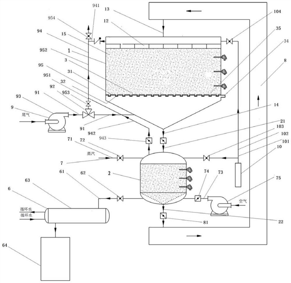
[0040] A circulating mobile adsorption device for adsorption materials for tail gas treatment, combined with figure 1 and Figure 13 As shown, it includes an adsorption tank 1 , a desorption tank 2 , an adsorption material delivery device 8 after desorption, a leveling device 12 and a discharge device 3 .

[0041] The adsorption tank 1 is filled with an adsorption material 15 for adsorption treatment of exhaust gas. The top of the adsorption tank 1 is provided with an adsorption tank feed pipe 13 , and the bottom end of the adsorption tank 1 is provided with an adsorption tank discharge pipe 14 .

[0042] The desorption tank 2 is used for receiving the adsorbed adsorption material 15 discharged from the adsorption tank 1 and performing desorption treatment on the adsorbed adsorption material 15 . The top of the desorption tank 2 is provided with a desorption tank feed pipe 21 , and the bottom end of the desorption tank 2 is provided with a desorption tank discharge pipe 22 . ...

Embodiment 2

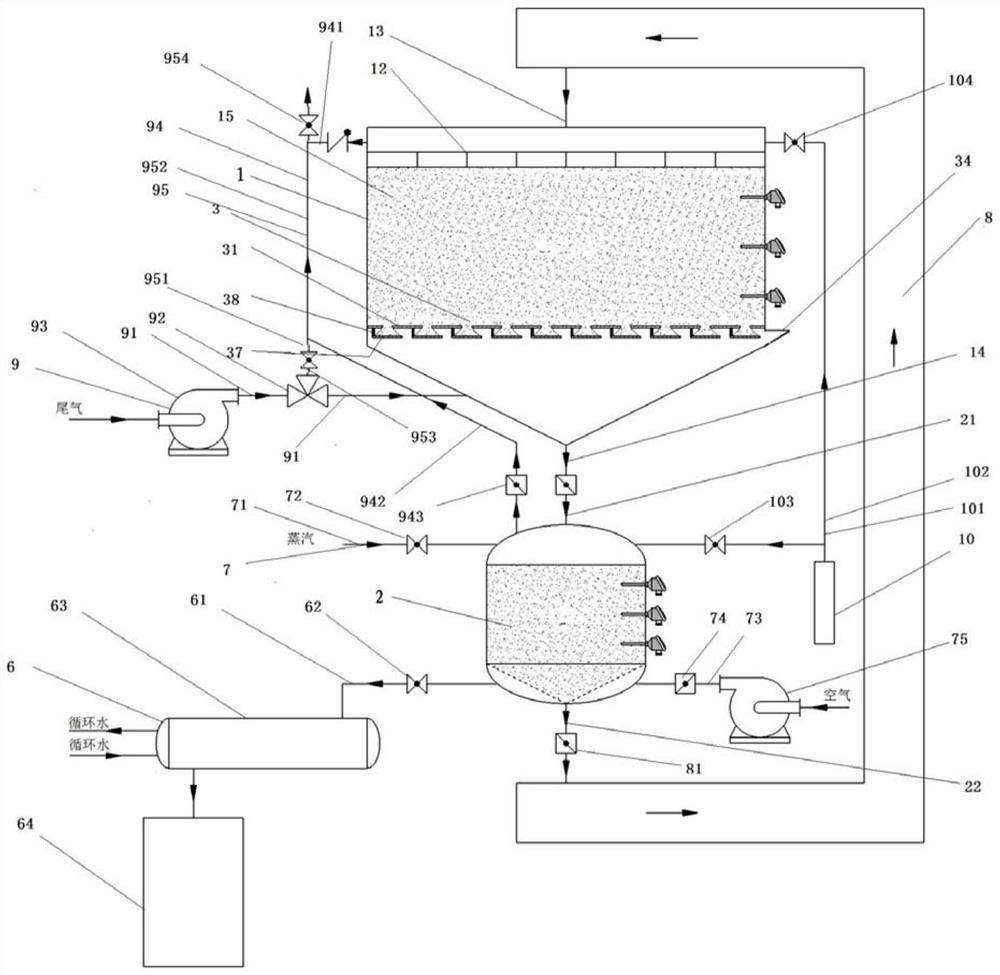
[0069] Based on the basis of embodiment 1, the difference between this embodiment and embodiment 1 is that the structure of the unloading device 3 changes, combining figure 2 and Figure 14 shown. That is, the unloading device 3 includes an upper grate 31, a chute 33, a lower grate 37, a movable scraper 38 and a scraper pushing mechanism 39.

[0070] The upper grate 31 is arranged inside the adsorption tank 1 for shielding the adsorption material 15 . A chute 33 for the sliding of the movable scraper 38 is provided on the left and right inner side walls of the adsorption tank 1 following the moving direction of the movable scraper 38, and the movable scraper 38 is driven by the scraper pushing mechanism 39 relative to the upper grate 31. The rectangular blanking opening of the suction tank moves to realize the accumulation and blanking operation of the adsorption material in the adsorption tank, and the scraper pushing mechanism 39 is fixedly arranged on the side wall of th...

Embodiment 3

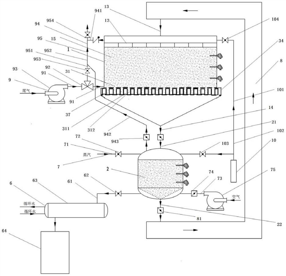
[0081] Based on the basis of embodiment 1, the difference between this embodiment and embodiment 1 is that the structure of the unloading device 3 changes, combining image 3 and Figure 15 shown. That is, the unloading device 3 includes an upper grate 31 and a lower grate 37, and the upper grate 31 and the lower grate 37 are fixedly arranged inside the adsorption tank 1 in parallel up and down, and are used to shield the adsorption material.

[0082] Conform to the movement direction of the movable material box 311 on the left and right side walls of the adsorption tank 1, respectively set up a chute 33 for the sliding of the material box pushing mechanism 313, and the movable material box 311 is driven by the material box pushing mechanism 313 relative to the upper grate 31 Move with the rectangular blanking opening of the lower grate 37 to realize the accumulation and blanking operation of the adsorption material in the feed bin, and the feed box pushing mechanism 313 is f...


PUM


Abstract

The invention discloses an adsorption material circulating moving type adsorption device for tail gas treatment. The device comprises an adsorption tank and a desorption tank, wherein the desorption tank is connected with the adsorption tank through a desorbed adsorption material conveying device, a desorption gas inlet device and a desorption tail gas treatment device are arranged on the desorption tank, a flattening device is arranged at the top end in the adsorption tank, a discharging device is arranged at the middle lower end in the adsorption tank, a tail gas inlet device is arranged onthe adsorption tank below the discharging device in a communicating manner, a tail gas exhaust device is arranged on the adsorption tank above the flattening device and at the bottom end of the desorption tank in a communicating manner, and a tail gas circulating device is arranged between the tail gas inlet device and the tail gas exhaust device. According to the invention, the adsorption tank and the desorption tank are separately arranged, and the discharging device arranged in the adsorption tank can ensure that an adsorption material subjected to adsorption operation can fall off in time,so that it is ensured that the adsorption material can be subjected to an adsorption reaction sufficiently, and cyclic movement of the adsorption material can be achieved.

Description

technical field [0001] The invention relates to the field of chemical reaction devices, and more specifically relates to a circulating and mobile adsorption device for an adsorption material for tail gas treatment. Background technique [0002] In petroleum, chemical, rubber, pesticide, dye, pharmaceutical, food, printing and dyeing and other production fields, exhaust gas will be generated during the production process. Exhaust gas contains components that pollute the environment and often have even high recovery value. If it is directly discharged into the atmosphere, it will cause environmental pollution and waste energy. Adsorbent materials can effectively absorb certain components from the tail gas, not only to purify the tail gas, but also to ensure that the valuable components in the tail gas are not wasted. [0003] At present, in most tail gas adsorption recovery and desorption regeneration devices, the position of the adsorption material is still, and the processe...

Claims


Application Information

Patent Timeline
IPC IPC(8): B01D53/02B01D53/00
CPCB01D53/002B01D53/02B01D2259/4009
Inventor 石伟东李迎军刘鹏飞
Owner 石伟东
Learn More