Metal wire machining system and method

A processing system, metal wire technology, applied in metal processing, metal processing equipment, manufacturing tools, etc., can solve problems such as conveying metal wires

Inactive Publication Date: 2021-02-23
周晓光
View PDF14 Cites 1 Cited by
  • Summary
  • Abstract
  • Description
  • Claims
  • Application Information

AI Technical Summary

Problems solved by technology

However, the device cannot convey

Method used


Image

  • Metal wire machining system and method
  • Metal wire machining system and method
  • Metal wire machining system and method

Examples


Example Embodiment

[0032] Specific implementation one:

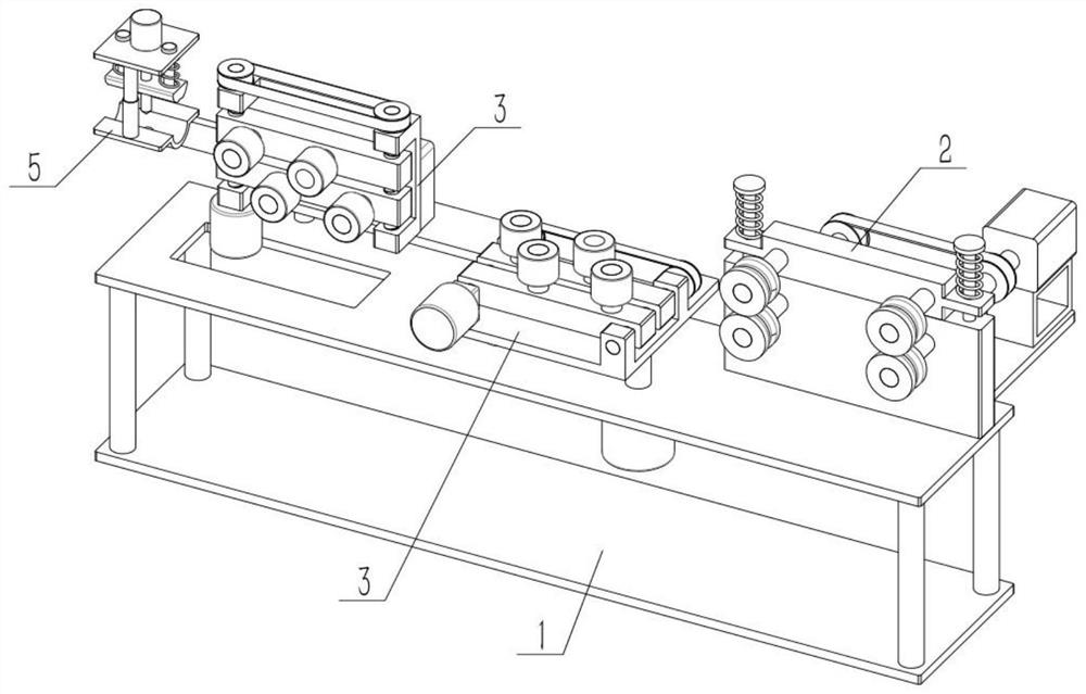
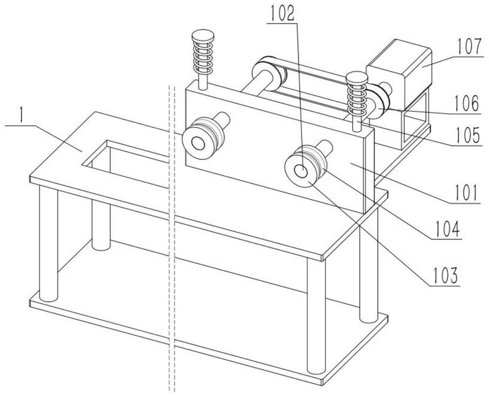
[0033] As shown in the figure, a metal wire processing system includes a support table 1, a shaft seat I101, a shaft I102, a driving stop wheel 103, a groove I104, a rod I105, a pulley I106, a motor I107, a displacement frame 2, a shaft II201 and The driven wire pulley 202, the upper end of the support table 1 is fixedly connected to the shaft seat I101, the shaft seat I101 is rotatably connected to two symmetrically arranged shafts I102, and the rear ends of the two shafts I102 are fixedly connected to an active limiting wheel 103, and two There are grooves I104 in the middle of the outer ring of the driving limiter pulley 103. The front ends of the two shafts I102 are fixed with a pulley I106. The two pulleys I106 are connected by belt transmission. The output shaft of the motor I107 is fixed with one of the shafts I102. connected, the motor I107 is fixed on the support table 1;

[0034] The upper end of the support table 1 is fixedly c...

Example Embodiment

[0035] Specific implementation two:

[0036]As shown in the figure, a groove II 203 is provided in the middle of the outer ring of each moving wire pulley 202 , and the two grooves II 203 are respectively mirror-symmetrical with the two grooves I 104 . The groove II 203 is convenient for the metal wire to be directly squeezed, which is convenient for initial placement. The combined use of the groove I 104 and the groove II 203 is convenient to increase the holding force when conveying metal wires of different diameters.

Example Embodiment

[0037] Specific implementation three:

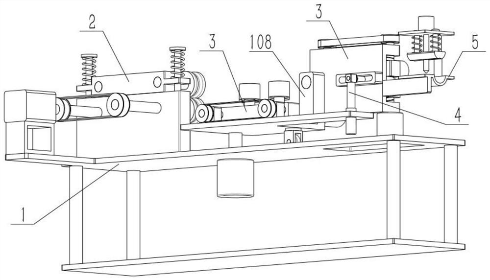
[0038] As shown in the figure, the metal wire processing system also includes a guiding mechanism, which includes a base 3, a bidirectional screw 301, a pulley II 302, a shaft seat II 303, a shaft III 304, an auxiliary wheel 305 and a motor II 307. The base 3 Two bidirectional lead screws 301 are connected in the upper rotation, the front ends of the two two-way lead screws 301 are fixedly connected to a pulley II 302, the two pulleys II 302 are connected by a belt drive, there are two shaft seats II 303, and two shaft seats II 303 are provided. It is screwed on two bidirectional lead screws 301, and the two shaft seats II 303 move in opposite directions. The upper end of each shaft seat II 303 is fixedly connected to two shafts III 304, and the two shafts III 304 are rotatably connected to an auxiliary wheel 305. Motor II 307 The output shaft is fixed with one of the two-way lead screws 301, the motor II 307 is fixed on the shaft seat I...


PUM


Abstract

The invention relates to wire machining, and particularly relates to a metal wire machining system and method. The metal wire machining system comprises a supporting table, a shaft seat I, a shaft I,a driving limiting wheel, a groove I, a rod I, a belt wheel I, a motor I, a displacement frame, a shaft II and a driven wire wheel, wherein the driving limiting wheel can enable metal wires to be conveyed leftwards, and then the metal wires with different diameters can be conveyed. The metal wires can be directly extruded into a groove II conveniently, initial placement is facilitated, and the groove I and the groove II are combined for use so that the holding force for conveying the metal wires with the different diameters can be increased conveniently. Two rows of auxiliary wheels are utilized for limiting the front sides and the rear sides of the metal wires, and the accuracy and stability of conveying of the metal wires on the horizontal plane are improved. A base swings to change theconveying direction, staggered arrangement is matched, during swinging and direction changing, the metal wires are uniform in stress point distribution and easy to bend and reverse, and conveying is stable after reversing. A vertically-arranged guide mechanism stabilizes the upper sides and the lower sides of the metal wires, then the circumferential stress points are distributed in the long direction, and the metal wires with the different diameters are conveyed stably and accurately.

Description

technical field [0001] The invention relates to wire rod processing, more specifically to a metal wire rod processing system and processing method. Background technique [0002] For example, the publication number is CN209597897U, a winding device for metal wire processing, which relates to the technical field of metal wire processing equipment; a second support is fixed on one side of the first support, and a speed-regulating motor is installed on the first support, and the speed-regulating motor and The main gear is driven and connected, the first driven gear is meshed above the main gear, and the second driven gear is meshed above the first driven gear. The main gear, the first driven gear and the second driven gear are respectively installed on the gear On the shaft, one end of the three gear shafts is respectively equipped with a bobbin mechanism; The ring is fixedly connected with the gear shaft; a guide wheel is installed on the guide wheel support; a number of bobbi...

Claims


Application Information

Patent Timeline
IPC IPC(8): B23B41/00B23Q7/00
CPCB23B41/00B23Q7/00
Inventor 周晓光
Owner 周晓光
Why Eureka
Try Eureka