Underground bent pipeline cutting equipment for sewage treatment
A technology for bending pipes and cutting equipment, applied in the field of underground bending pipe cutting equipment for sewage treatment, can solve the problems of inaccuracy, insecurity, time-consuming and labor-intensive, etc., and achieve the effect of simple and convenient operation, time-saving and labor-saving operation.
- Summary
- Abstract
- Description
- Claims
- Application Information
AI Technical Summary
Problems solved by technology
Method used
Image

Examples
Embodiment 1
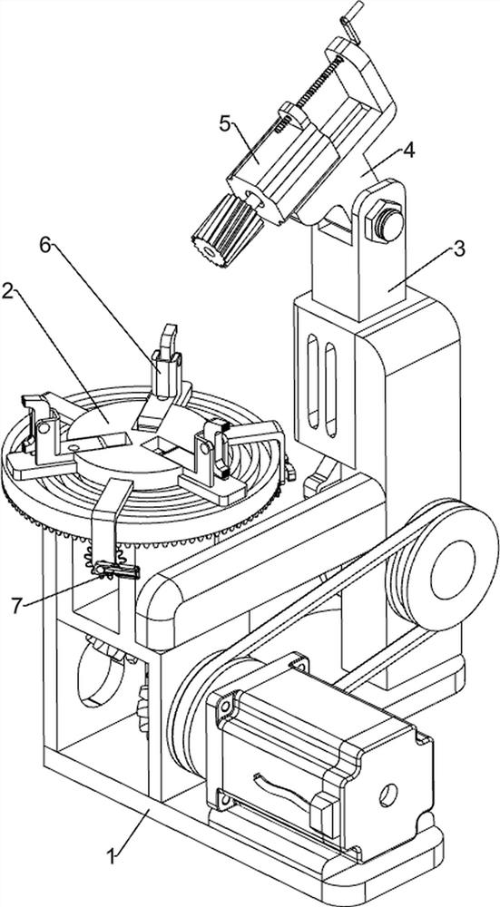
[0065] An underground curved pipe cutting device for sewage treatment, such as figure 1 and image 3 As shown, it includes an installation base plate 1, a rotating mechanism 2, a sliding mechanism 3, a first adjusting mechanism 4 and a cutting mechanism 5. The upper front part of the installation base plate 1 is provided with a rotation mechanism 2, and the installation base plate 1 is provided with a sliding mechanism 3. The mechanism 3 is connected with the rotating mechanism 2 , the sliding mechanism 3 is provided with a first adjusting mechanism 4 , and the first adjusting mechanism 4 is provided with a cutting mechanism 5 .
[0066]Manual cutting of pipes is inaccurate, time-consuming and labor-intensive and unsafe. This equipment can cut automatically, which is accurate, time-saving, labor-saving and safe. First, people put the pipe in the rotating mechanism 2, and then adjust the first adjustment according to the height of the pipe. Mechanism 4, then adjust the cutting...
Embodiment 2
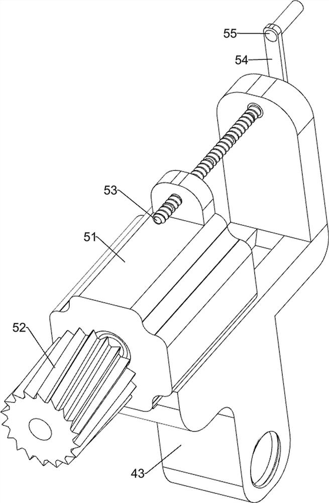
[0068] On the basis of Example 1, such as figure 2 , image 3 , Figure 4 , Figure 5 , Image 6 and Figure 7 As shown in the figure, the rotating mechanism 2 includes a servo motor 21, a first rotating shaft 22, a second rotating shaft 23, a bevel gear set 24 and a notch disc 25, and the right side of the front part on the installation base plate 1 is equipped with a servo motor 21, and the servo motor 21 The output shaft is connected with the sliding mechanism 3, the front part of the installation base plate 1 is rotatably provided with a first rotating shaft 22, the first rotating shaft 22 is connected with the output shaft of the servo motor 21, and the upper and lower sides of the front side of the installation base plate 1 are rotationally connected. There is a second rotating shaft 23, a bevel gear set 24 is arranged at the bottom of the second rotating shaft 23, the bevel gear set 24 is connected with the first rotating shaft 22, and a notched disk 25 is arranged...
Embodiment 3
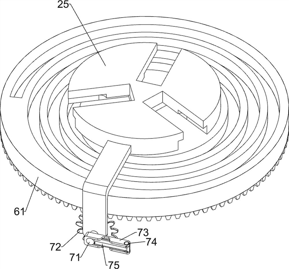
[0077] On the basis of Example 2, such as figure 1 , Image 6 and Figure 7 As shown, a clamping mechanism 6 is also included. The clamping mechanism 6 is provided with a clamping mechanism 6 on the second rotating shaft 23. The clamping mechanism 6 cooperates with the notch disc 25. The clamping mechanism 6 includes a second disc 61 , the second fixed seat 63, the fixed rod 64, the fifth rotating shaft 65 and the fixing clip 66, the second rotating shaft 23 is provided with a second disc 61 for rotation, and the second disc 61 is located between the notch disc 25 and the installation base plate 1 Between, the top of the second disc 61 is provided with a spiral groove 62, and three second fixing seats 63 are slidably arranged on the gap disc 25, and the bottoms of the three second fixing seats 63 are all provided with fixing rods 64, and the fixing rods 64 and the first fixing rods are connected to each other. The spiral grooves 62 on the two disks 61 cooperate, and the tops...
PUM
 Abstract
Description
Claims
Application Information
 - R&D
- Intellectual Property
- Life Sciences
- Materials
- Tech Scout
- Unparalleled Data Quality
- Higher Quality Content
- 60% Fewer Hallucinations
Browse by: Latest US Patents, China's latest patents, Technical Efficacy Thesaurus, Application Domain, Technology Topic, Popular Technical Reports.
© 2025 PatSnap. All rights reserved.Legal|Privacy policy|Modern Slavery Act Transparency Statement|Sitemap|About US| Contact US: help@patsnap.com