Bevel chamfering equipment for bulletproof glass fiber plate
A technology of bulletproof glass fiber board and chamfer angle, which is applied in the direction of using liquid separation agent, separation method, and separation of dispersed particles, which can solve the problems of time-consuming, manual loading and unloading, etc., and achieve simple and convenient operation, good adsorption effect, and reduce The effect of manual feeding
- Summary
- Abstract
- Description
- Claims
- Application Information
AI Technical Summary
Problems solved by technology
Method used
Image

Examples
Embodiment 1
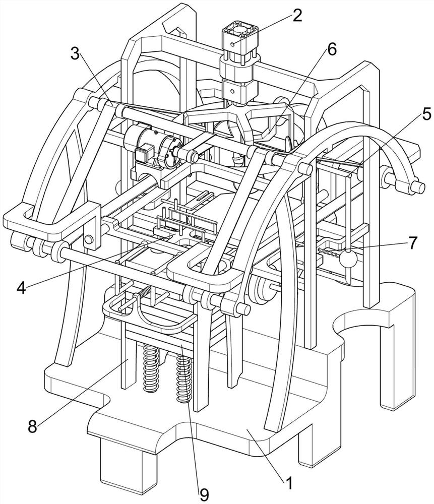
[0073]A chamfering equipment for bulletproof fiberglass panels, such as figure 1 and figure 2 As shown, it includes a bottom plate 1, a cutting mechanism 2, a moving mechanism 3 and an adsorption mechanism 4. The cutting mechanism 2 is arranged on the upper and rear side of the bottom plate 1, the moving mechanism 3 is arranged on the bottom plate 1, and the adsorption mechanism 4 is arranged at the rear of the moving mechanism 3. .
[0074] When people need to chamfer the bulletproof fiberglass board, they can use this chamfering equipment for the bulletproof fiberglass board. The glass fiber board is adsorbed, and then the moving mechanism 3 is started, and the moving mechanism 3 moves backward to drive the adsorption mechanism 4 to move backward, thereby driving the bulletproof glass fiber board to move backward. When the bulletproof glass fiber board is moved to the cutting mechanism 2, The bullet-proof fiberglass board breaks away from the adsorption mechanism 4 and fa...
Embodiment 2
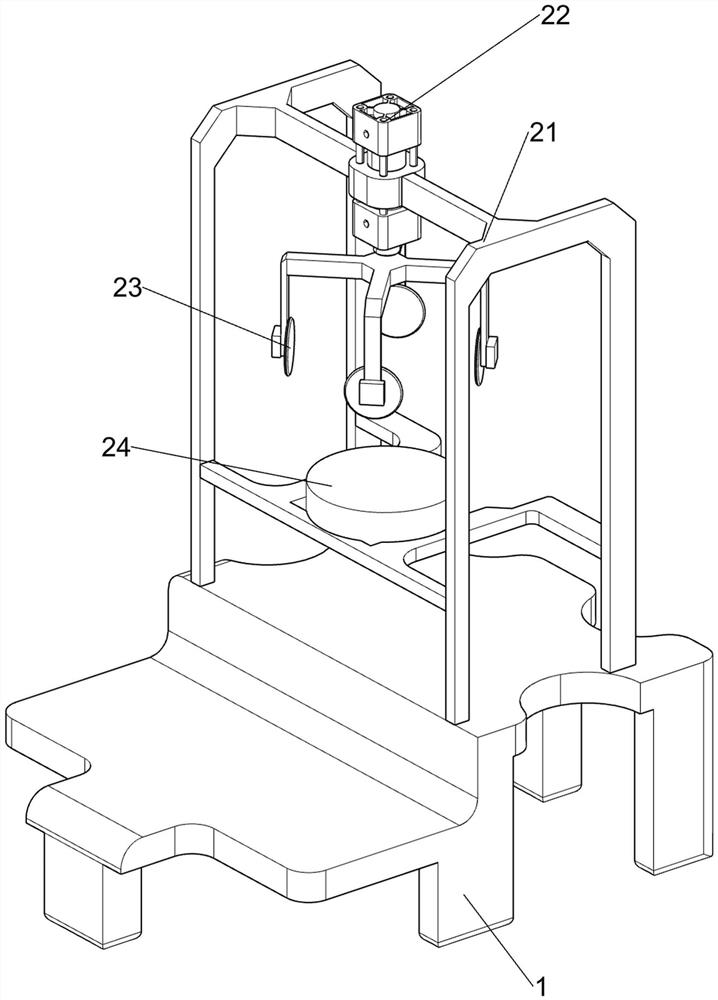
[0076] On the basis of Example 1, such as Figure 3-5 As shown, the cutting mechanism 2 includes a mounting frame 21, a cylinder 22, an electric cutter 23 and a bearing plate 24, the upper rear side of the bottom plate 1 is provided with a mounting frame 21, and a cylinder 22 is installed on the mounting frame 21, and the cylinder 22 is connected on the telescopic rod. An electric cutter 23 is arranged, and the mounting frame 21 is provided with a bearing plate 24 .
[0077] After closing the moving mechanism 3, people start the cylinder 22, and the telescopic rod of the cylinder 22 drives the electric cutter 23 to reciprocate up and down, and the electric cutter 23 moves downward to chamfer the bulletproof glass fiber board, achieving the effect of automatic cutting, and the operation is simple and convenient. People control cylinder 22 telescopic rods to move upwards after pouring bevel, thereby electric cutter 23 moves upwards, closes cylinder 22 subsequently.
[0078] The...
Embodiment 3
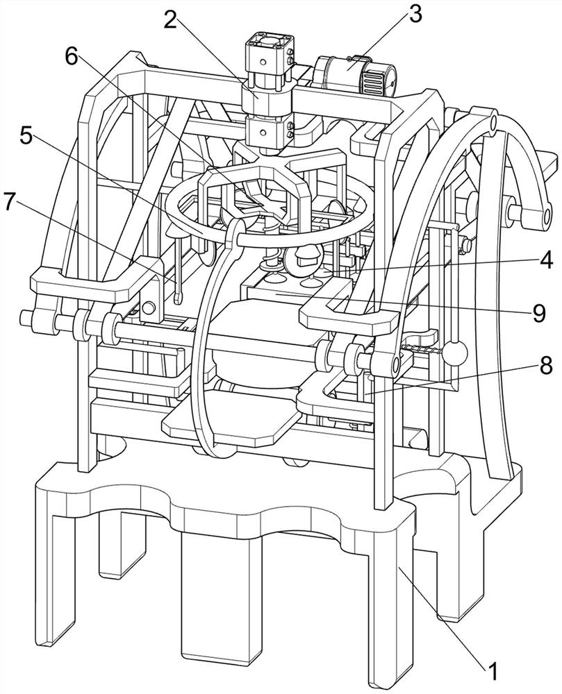
[0083] On the basis of Example 2, such as Figure 6-9 As shown, a dust reduction mechanism 5 is also included. The dust reduction mechanism 5 includes a second fixed frame 51, a liquid storage tank 52, a catheter 53 and an atomizing nozzle 54. The rear side of the mounting frame 21 is provided with a second fixed frame 51. A liquid storage tank 52 is installed on the lower side of the second fixing frame 51 , and the left and right sides of the liquid storage tank 52 are provided with catheters 53 , and an atomizing nozzle 54 is connected between the two catheters 53 and the second fixing frame 51 .
[0084] The water in the liquid storage tank 52 is ejected through the atomizing nozzle 54 under the action of the catheter 53, thereby reducing the dust generated during the chamfering of the electric cutter 23, thus achieving the effect of reducing dust.
[0085] Also includes fixed mechanism 6, and fixed mechanism 6 includes connecting frame 61, telescoping rod 62, top block 63...
PUM
 Abstract
Description
Claims
Application Information
 - R&D
- Intellectual Property
- Life Sciences
- Materials
- Tech Scout
- Unparalleled Data Quality
- Higher Quality Content
- 60% Fewer Hallucinations
Browse by: Latest US Patents, China's latest patents, Technical Efficacy Thesaurus, Application Domain, Technology Topic, Popular Technical Reports.
© 2025 PatSnap. All rights reserved.Legal|Privacy policy|Modern Slavery Act Transparency Statement|Sitemap|About US| Contact US: help@patsnap.com