Steel pipe external thread turning equipment for high-precision machining
A technology of high-precision processing and external thread, which is applied in metal processing equipment, manufacturing tools, thread cutting devices, etc., can solve the problems of deformation of steel pipe external screw and loss of processing cost of steel pipe external screw, etc., to reduce labor intensity, reduce manpower, reduce The effect of cost loss
- Summary
- Abstract
- Description
- Claims
- Application Information
AI Technical Summary
Problems solved by technology
Method used
Image
Examples
Embodiment 1
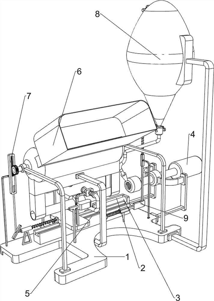
[0062]A high-precision machining steel pipe outer threaded equipment, such asfigure 1 As shown, including the bottom plate 1, the stent 2, the cylinder 3, the vehicle threaded mechanism 4, and the step of the push mechanism 5 are provided, and the bottom plate 1 is provided with a stent 2, and the bracket 2 is mounted on the bracket 2, and the bottom plate 1 is provided. The threaded mechanism 4, and the bottom plate 1 is provided with a stepped drive mechanism 5.
[0063]When people need to process the steel pipe external thread, people will be placed outside the steel pipe externally needed to be processed within the push mechanism 5, and when the steel pipe external thread is clamped by stepped up the promotion mechanism 5, people turn on the cylinder 3, while One of the car threaded mechanisms 4 is turned to rotate, and the telescopic rod of the cylinder 3 drives the push mechanism 5, and when the retractable rod of the cylinder 3 drives the push mechanism 5 to move the steel tube ...
Embodiment 2
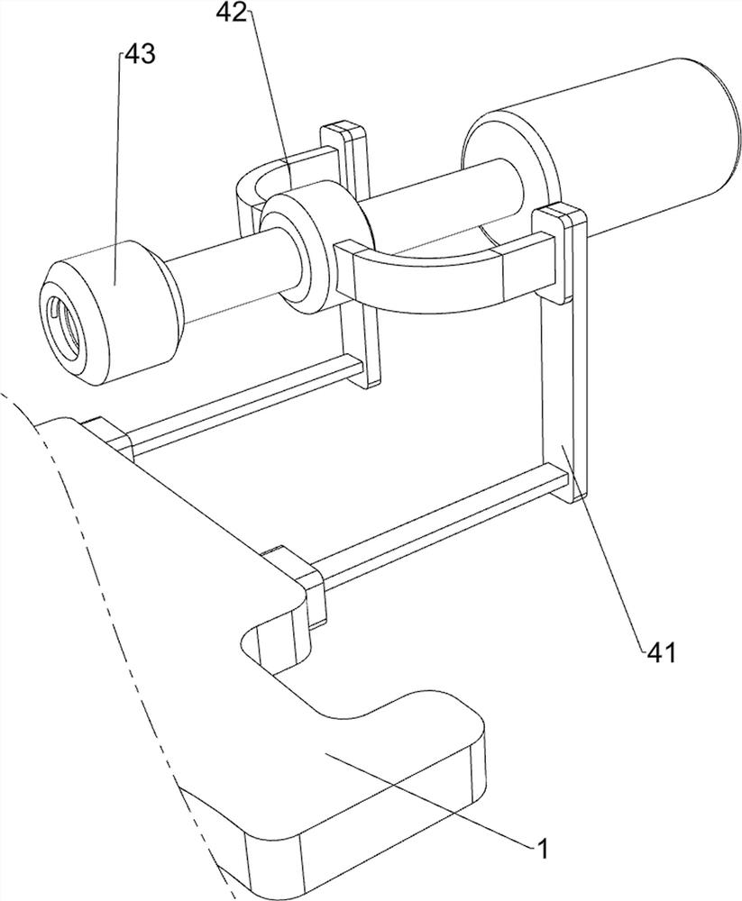
[0065]On the basis of Example 1, such asfigure 2 As shown, the car threaded mechanism 4 includes a support plate 41, a first rotating sleeve 42, and a car threaded assembly 43, and both the bottom plate 1 is provided with a support plate 41, and the two support plates 41 are provided with a first glove. 42. The first bushing 42 is installed with a car threaded assembly 43.
[0066]When a steel pipe is applied to the push mechanism 5, and people open the cylinder 3 and the car thread assembly 43, the bus thread assembly 43 is rotated, and the retractable rod of the cylinder 3 is supported to the right side. When moving, the steel tube is moved to the right side. At this time, the outer thread of the steel pipe is in contact with the car threaded assembly 43, so that the car threaded assembly 43 processes the steel pipe exterior, and when the steel pipe is completed, the cylinder 3 The telescopic rod drives the push mechanism 5 to move to the left side, so that the push mechanism 5 moves...
Embodiment 3
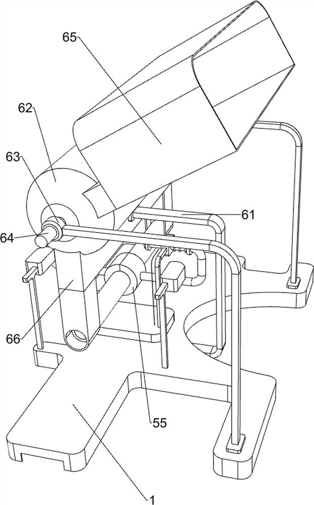
[0068]On the basis of Example 2, such asfigure 1 ,image 3 ,Figure 4 ,Figure 5 ,Figure 6 withFigure 7As shown, the push mechanism 5 includes a first guiding sleeve 51, a slide plate 52, a fixing sleeve 53, a second guide sleeve 54, a tensioning sleeve 55, a compression spring 56, and a fixed card block 57, and the bottom plate 1 is provided. The first guide sleeve 51, the first guide sleeve 51 slides the sliding plate 52, and the bottom side of the slide plate 52 is provided with a fixed sleeve 53, and the fixing sleeve 53 is connected to the telescopic rod of the cylinder 3, and the slide plate 52 is on the left side. Both are provided with a second guiding sleeve 54, and the two second guide 54 are slidably provided with a card tight sleeve 55, and the two card tight sleeve 55 has a compression spring 56, and the compression spring 56 is respectively The second guide sleeve 54 and the card tight sleeve 55 are connected, and the front and rear two parts on the left side of the botto...
PUM
 Abstract
Description
Claims
Application Information
 - R&D
- Intellectual Property
- Life Sciences
- Materials
- Tech Scout
- Unparalleled Data Quality
- Higher Quality Content
- 60% Fewer Hallucinations
Browse by: Latest US Patents, China's latest patents, Technical Efficacy Thesaurus, Application Domain, Technology Topic, Popular Technical Reports.
© 2025 PatSnap. All rights reserved.Legal|Privacy policy|Modern Slavery Act Transparency Statement|Sitemap|About US| Contact US: help@patsnap.com


