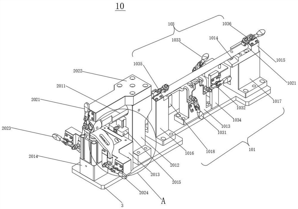
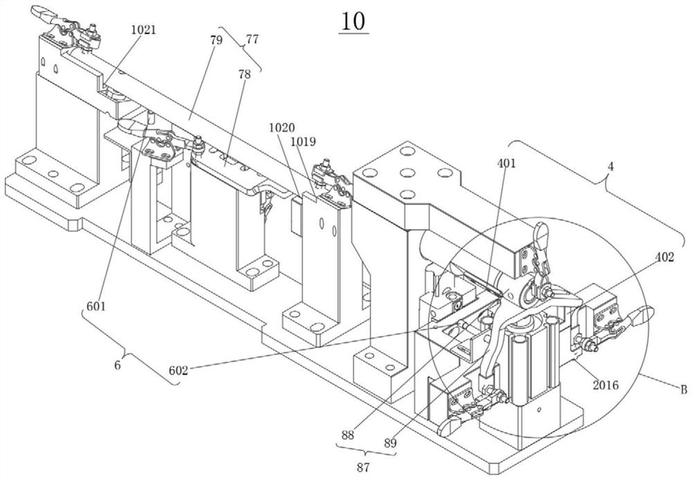
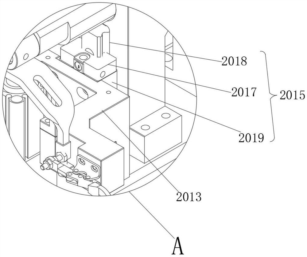
Shifting fork assembly combined welding clamp and shifting fork assembly combined welding system

A welding fixture and assembly technology, applied in welding equipment, laser welding equipment, manufacturing tools, etc., can solve problems such as hidden safety hazards, difficulty in normal driving, unstable welding quality, etc., to avoid installation accuracy problems and reduce labor costs , The effect of improving welding efficiency

Active Publication Date: 2021-02-23
HANS LASER TECH IND GRP CO LTD +1
View PDF6 Cites 2 Cited by
  • Summary
  • Abstract
  • Description
  • Claims
  • Application Information

AI Technical Summary

Problems solved by technology

[0003] Among them, the forward gear shift fork assembly and the fifth and sixth gear shift fork assemblies are an important part of the shift fork system, and their related manufacturing and processing techniques have been continuously improved and developed. However, the existing welding process of the shift fork assembly It is easy to cause the overall strength of the welding seam of the shift fork assembly to be low. At the same time, due to the instability of the welding quality, the weld seam often breaks, which seriously shortens the service life of the shift fork assembly. It is very easy to be difficult to cope with some normal driving or sudden driving needs because of the inability to change the speed in time, thus bringing great safety hazards to oneself and others
[0004] In addition, the existing welding of the shift fork assembly usually requires multiple clamping and separate welding, the efficiency is relatively low, and the labor cost is relatively large.

Method used


Image

  • Shifting fork assembly combined welding clamp and shifting fork assembly combined welding system
  • Shifting fork assembly combined welding clamp and shifting fork assembly combined welding system
  • Shifting fork assembly combined welding clamp and shifting fork assembly combined welding system

Examples


Embodiment Construction

[0031] Unless otherwise defined, all technical and scientific terms used herein have the same meaning as commonly understood by those skilled in the technical field of the application; the terms used herein in the description of the application are only for the purpose of describing specific embodiments , is not intended to limit the present application; the terms "comprising" and "having" and any variations thereof in the description and claims of the present application and the description of the above drawings are intended to cover non-exclusive inclusion. The terms "first", "second" and the like in the description and claims of the present application or the above drawings are used to distinguish different objects, rather than to describe a specific order.

[0032] Reference herein to an "embodiment" means that a particular feature, structure, or characteristic described in connection with the embodiment can be included in at least one embodiment of the present application....


PUM


Abstract

The invention discloses a shifting fork assembly combined welding clamp which comprises a forward gear shifting fork assembly clamp, a fifth-sixth gear shifting fork assembly clamp and a base, and theforward gear shifting fork assembly clamp and the fifth-sixth gear shifting fork assembly clamp are fixedly installed on the base. The forward gear shifting fork assembly clamp is used for fixing anautomobile forward gear shifting fork assembly and comprises a forward gear positioning mechanism and a forward gear locking mechanism. The forward gear positioning mechanism is arranged on the base,and the forward gear locking mechanism is arranged on the forward gear positioning mechanism. The fifth-sixth gear shifting fork assembly clamp is used for fixing an automobile fifth-sixth gear shifting fork assembly and comprises a fifth-sixth gear positioning mechanism and a fifth-sixth gear locking mechanism. The fifth-sixth gear positioning mechanism is arranged on the base and adjacent to theforward gear positioning mechanism, and the fifth-sixth gear locking mechanism is arranged on the fifth-sixth gear positioning mechanism. According to the shifting fork assembly combined welding clamp and the shifting fork assembly combined welding system, the welding efficiency, the welding precision and the automation degree of an automobile forward gear and fifth-sixth gear shifting fork assembly welding process are improved, and the labor cost is reduced.

Description

technical field [0001] The present application relates to the technical field of shift fork processing, and more specifically, relates to a shift fork assembly combined welding fixture and a shift fork assembly combined welding system. Background technique [0002] As the use of automobiles becomes more and more popular, users have higher and higher requirements for the performance of automobiles. The shift fork is a part of the automobile gearbox, connected with the shift handle, located at the lower end of the shift handle, and the user controls the shift handle. At the same time, the speed change handle drives the shift fork to move the corresponding speed change wheel, so that the input / output speed ratio is changed. [0003] Among them, the forward gear shift fork assembly and the fifth and sixth gear shift fork assemblies are an important part of the shift fork system, and their related manufacturing and processing techniques have been continuously improved and develop...

Claims


Application Information

Patent Timeline
Patent Type & Authority Applications(China)
IPC IPC(8): B23K26/02B23K26/21B23K26/70
CPCB23K26/02B23K26/21B23K26/702
Inventor 邹春江潘佐梅唐景龙曹文辉王文政于成松甘伟彪曹明辉赵斌范文增徐华钊陈炜越陈根余陈焱高云峰
Owner HANS LASER TECH IND GRP CO LTD
Why Eureka
Try Eureka