A corrugated metal hose net sleeve compression ring locking device and method

A metal hose and locking device technology, applied in auxiliary devices, metal processing equipment, auxiliary welding equipment, etc., can solve the problems of affecting the effect of the head, the non-folding of the mesh sleeve, poor universality of the rigid mold, etc., and improve the deformation amount. Insufficient, difficult to improve welding, easy welding effect

Active Publication Date: 2021-08-13
XI AN JIAOTONG UNIV
View PDF1 Cites 0 Cited by
  • Summary
  • Abstract
  • Description
  • Claims
  • Application Information

AI Technical Summary

Problems solved by technology

However, the inner diameter of the external mold is greater than or equal to the outer diameter of the compression ring of the mesh sleeve, and when the compression ring of the mesh sleeve is initially deformed, there is no internal constraint, and the plastic deformation of the bellows, the mesh sleeve, and the compression ring of the mesh sleeve is insufficient, and the strength is insufficient. Insufficient, the effect of the head is not good; in addition, there is no internal restraint in the early stage, and the net sleeve and the net sleeve pressing ring tend to bend inward. When the internal mold of the overall mold is pressed in later, the net sleeve is easy to cause the net sleeve to not fold inward.
These all affect the effect of the head, and there are also quality risks in the next step of joint welding. In addition, the overall rigid mold has poor versatility and is not suitable for batch flexible production of bellows with different calibers.

Method used


Image

  • A corrugated metal hose net sleeve compression ring locking device and method
  • A corrugated metal hose net sleeve compression ring locking device and method
  • A corrugated metal hose net sleeve compression ring locking device and method

Examples


Embodiment Construction

[0035] The present invention will be described in detail below in conjunction with the accompanying drawings and embodiments.

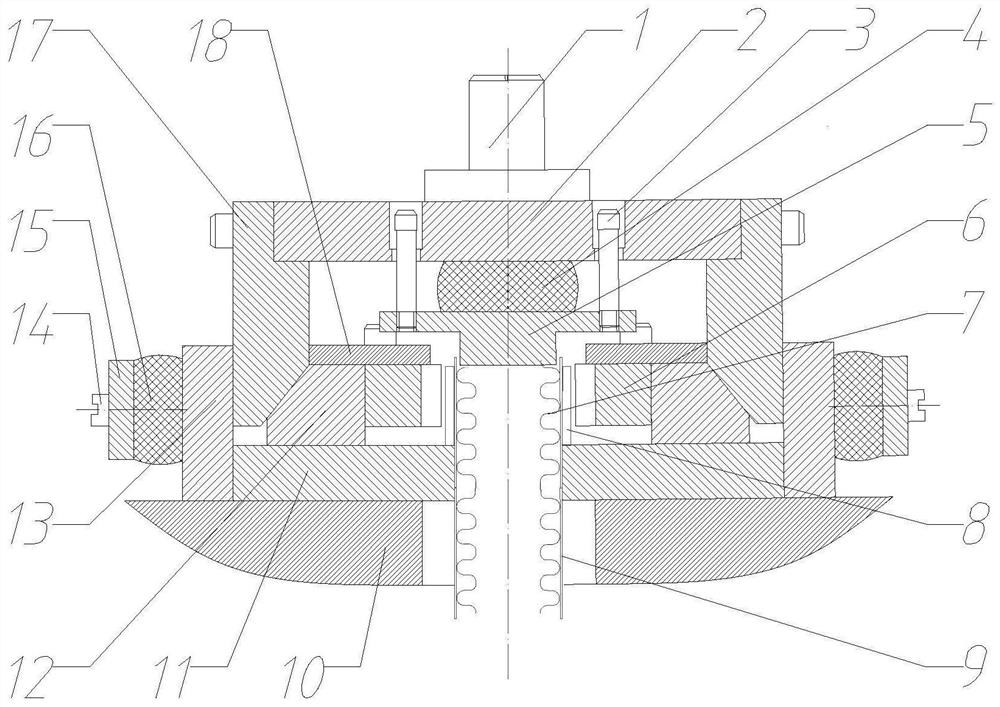
[0036] refer to figure 1, a corrugated metal hose net sleeve compression ring locking device, including a driving part and a driven part;

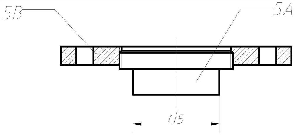
[0037] The active part includes a mold handle 1, an upper mold frame 2, a first guide column 3, a first elastic element 4, an upper mold frame 5 and a wedge 17; It is connected with the upper end of the first guide post 3, and the lower end of the first guide post 3 is fixedly connected with the upper mold 5. The first guide post 3 can move up and down in the guide post installation hole of the upper mold frame 2, but is limited by the upper end of the first guide post 3. Constrained with the upper mold 5, the first guide post 3 does not break away from the guide post installation hole; the first elastic element 4 is arranged between the upper mold frame 2 and the upper mold 5, and the first elastic element 4 is ...


PUM


Abstract

A corrugated metal hose net sleeve compression ring locking device and method, including a mold handle, the mold handle is fixedly connected to the upper mold frame, the upper mold frame is fixedly connected to the upper mold through the first guide column, and the upper mold frame is connected to the upper mold There is a first elastic element between them, and the outer side of the upper mold frame is fixedly connected with the upper end of the wedge; the lower slope of the wedge is matched with the outer slope of the slider, and the inner side of the slider is fixedly connected with the replaceable lower mold of the split mold, and the slider and the lower There is a fixed limit plate on the top of the mold, and the outer side of the limit plate cooperates with the inner side of the wedge; the slider is placed on the radial guide positioning device, and the outer side of the radial guide positioning device cooperates or is fixedly connected with the inner side of the baffle; the upper part of the inner side of the baffle and The outer side of the lower end of the wedge is matched, the second elastic element and the end cover are arranged on the outer side of the baffle in turn, and the second guide post passes through the end cover and the baffle to be fixedly connected with the slider; the existing end faces of the three parts are changed by adjustable plastic deformation , Obtain enough plastic deformation to make these three parts fit closely, ensure the assembly consistency of the bellows, net sleeve, and net sleeve compression ring, and achieve the effect of the head.

Description

technical field [0001] The invention belongs to the technical field of advanced material forming, and in particular relates to a compression ring locking device and method for a corrugated metal hose net sleeve. Background technique [0002] Corrugated metal hoses are mainly used for the transportation of various liquids and gases and the compensation of piping installation errors. The corrugated metal hoses are made of comprehensive metal materials that are resistant to high and low temperature, high pressure, corrosion, aging, wear, and are fully sealed without holes. properties, and the flexibility of the corrugated structure, the application range is very wide. For example, the transportation of clean gas in the semiconductor medical industry; the demand for high-temperature environments in the metallurgy and electric power industries; the transportation of acids and alkalis in the petrochemical industry; the application of extreme temperature difference resistance and m...

Claims


Application Information

Patent Timeline
Patent Type & Authority Patents(China)
IPC IPC(8): B23K31/02B23K37/00B23K37/053
CPCB23K31/02B23K37/00B23K37/053
Inventor 张大伟冯智彦赵升吨
Owner XI AN JIAOTONG UNIV
Why Eureka
Try Eureka