Die end face machining device and machining method thereof

An end-face machining and mold technology, which is applied in metal processing equipment, manufacturing tools, grinding workpiece supports, etc., can solve problems such as poor versatility, and achieve the effect of thorough grinding, improving processing range and saving costs.

Inactive Publication Date: 2021-02-23
苏州锦坤模塑有限公司
View PDF9 Cites 2 Cited by
  • Summary
  • Abstract
  • Description
  • Claims
  • Application Information

AI Technical Summary

Problems solved by technology

[0004] The object of the present invention is to provide a mold end surface processing device and its processing method to solve the problem that the existing mold end surface processing device proposed in the above background technology can only process molds of the same size and has poor versatility

Method used


Image

  • Die end face machining device and machining method thereof
  • Die end face machining device and machining method thereof
  • Die end face machining device and machining method thereof

Examples


Embodiment Construction

[0030] The following will clearly and completely describe the technical solutions in the embodiments of the present invention with reference to the accompanying drawings in the embodiments of the present invention. Obviously, the described embodiments are only some, not all, embodiments of the present invention.

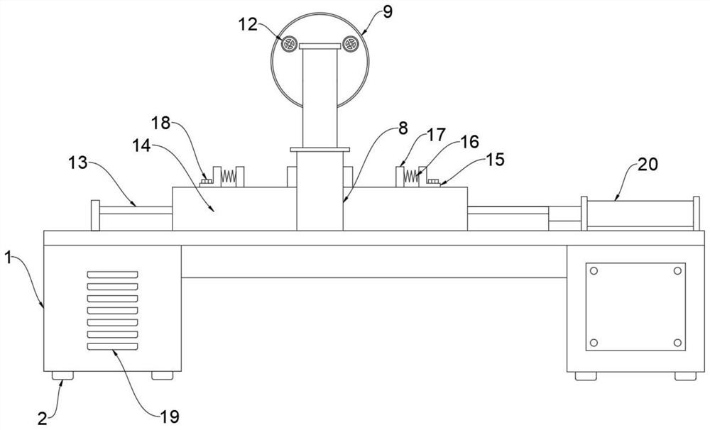
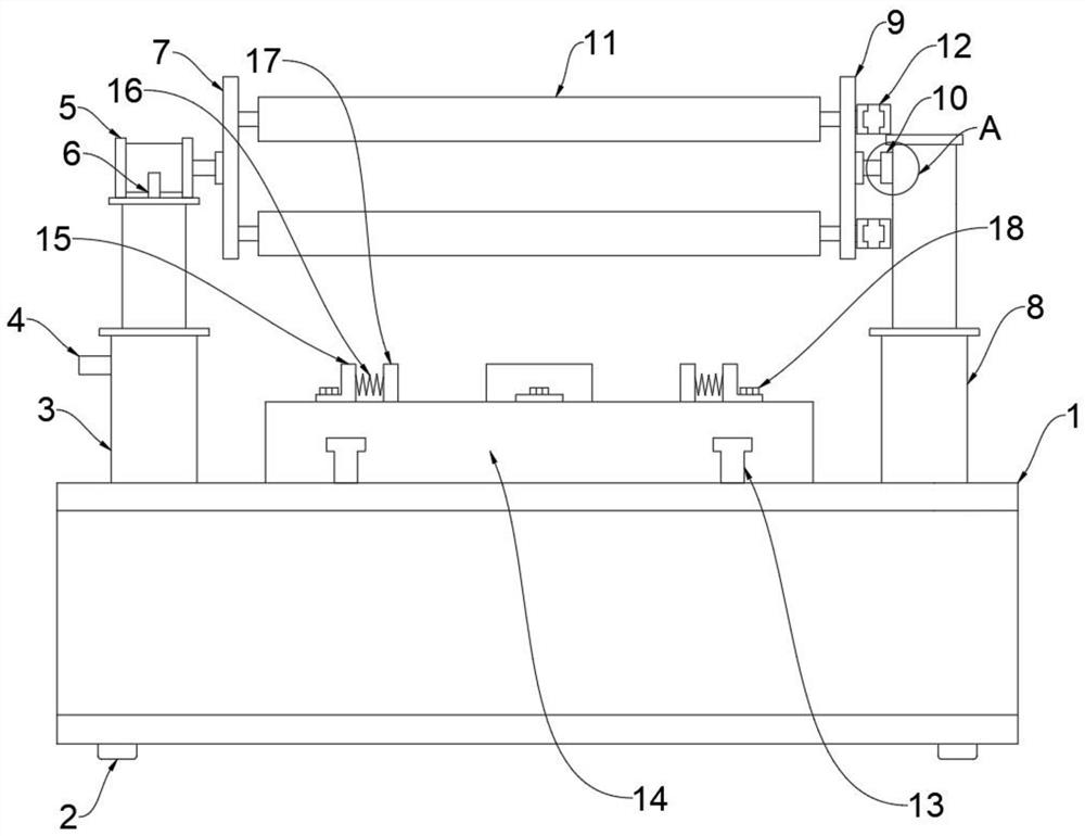
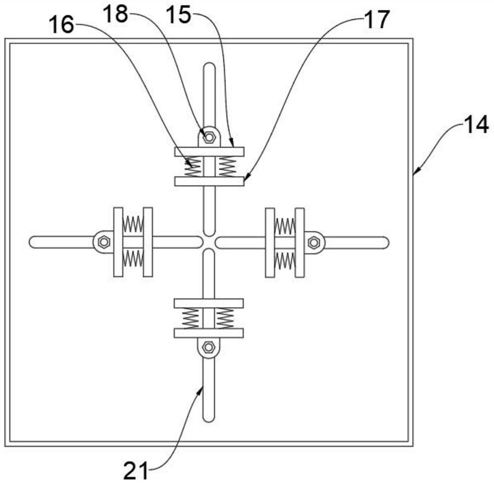
[0031] see Figure 1-5 , an embodiment provided by the present invention: a mold end surface processing device, including a cabinet body 1, the front end of the cabinet body 1 is provided with heat dissipation louvers 19, and seven heat dissipation louvers 19 are provided, and the heat dissipation louvers 19 can be cabinet body 1 The internal electrical mechanism dissipates heat to prolong the service life. The upper surface of the cabinet body 1 is provided with a guide rail 13, and there are two guide rails 13. A workbench 14 is installed above the guide rail 13. The guide rail 13 can guide the workbench 14 to move and work The front end above the platform 14 is eq...


PUM


Abstract

The invention discloses a die end face machining device and a machining method thereof, and relates to the technical field of die machining. The device and the method aim at solving the problems thatan existing die end face machining device can only machine dies of the same size and is poor in universality. The device is characterized in that heat dissipation shutters are arranged at the front end of a cabinet body, seven heat dissipation shutters are arranged, guide rails are arranged on the upper surface of the cabinet body, two guide rails are arranged, a workbench is installed above the guide rails, a linkage column is installed at the front end of the upper portion of the workbench, a second rotating disc is installed above the linkage column, a hydraulic column is installed at the rear end of the upper portion of the workbench, a liquid inlet is formed in the outer wall of the hydraulic column, a stepping motor is installed above the hydraulic column, the stepping motor is fixedly connected with the hydraulic column through a motor support, and a first rotating disc is installed at the output end of the stepping motor.

Description

technical field [0001] The invention relates to the technical field of mold processing, in particular to a mold end surface processing device and a processing method thereof. Background technique [0002] The mold is a tool that makes the blank into a specific shape and size under the action of external force. Widely used in blanking, extrusion, powder metallurgy parts pressing, pressure casting, and compression molding or injection molding of engineering plastics, rubber, ceramics and other products. The mold has a specific contour or inner cavity shape, and the application of the contour shape with cutting edges can separate the blank according to the contour line shape, and the application of the inner cavity shape can make the blank obtain a corresponding three-dimensional shape. The mold generally includes two parts, the movable mold and the fixed mold, which can be separated or combined. Take out the parts when they are separated, and inject the blank into the mold c...

Claims


Application Information

Patent Timeline
Patent Type & Authority Applications(China)
IPC IPC(8): B24B19/20B24B41/06B24B41/00
CPCB24B19/20B24B41/06B24B41/00
Inventor 葛安军
Owner 苏州锦坤模塑有限公司
Why Eureka
Try Eureka