
Hot runner oil cylinder cooling structure and mounting method thereof

A technology of cooling structure and hot runner, which is applied in the cooling field of hot runner of injection mold, can solve the problems of easy failure of water cooling, achieve the effect of reducing processing accuracy and avoiding extrusion deformation

Active Publication Date: 2021-02-23
DONGFENG HONDA AUTOMOBILE CO LTD
View PDF15 Cites 0 Cited by
  • Summary
  • Abstract
  • Description
  • Claims
  • Application Information

AI Technical Summary

Problems solved by technology

[0003] The purpose of the present invention is to provide a hot runner oil cylinder cooling structure and its installation method for the problem that water cooling is prone to failure

Method used


Image

  • Hot runner oil cylinder cooling structure and mounting method thereof
  • Hot runner oil cylinder cooling structure and mounting method thereof
  • Hot runner oil cylinder cooling structure and mounting method thereof

Examples


Embodiment Construction

[0022] The following specific implementation methods are used to explain the technical solutions of the claims of the present invention, so that those skilled in the art can understand the claims. The protection scope of the present invention is not limited to the following specific implementation structures. The protection scope of the present invention includes the technical solution of the claims of the present invention made by those skilled in the art and is different from the following specific embodiments.

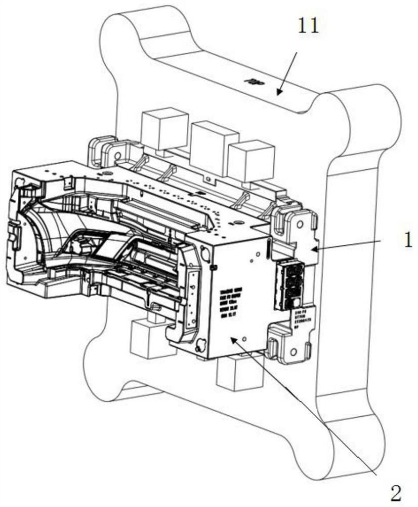
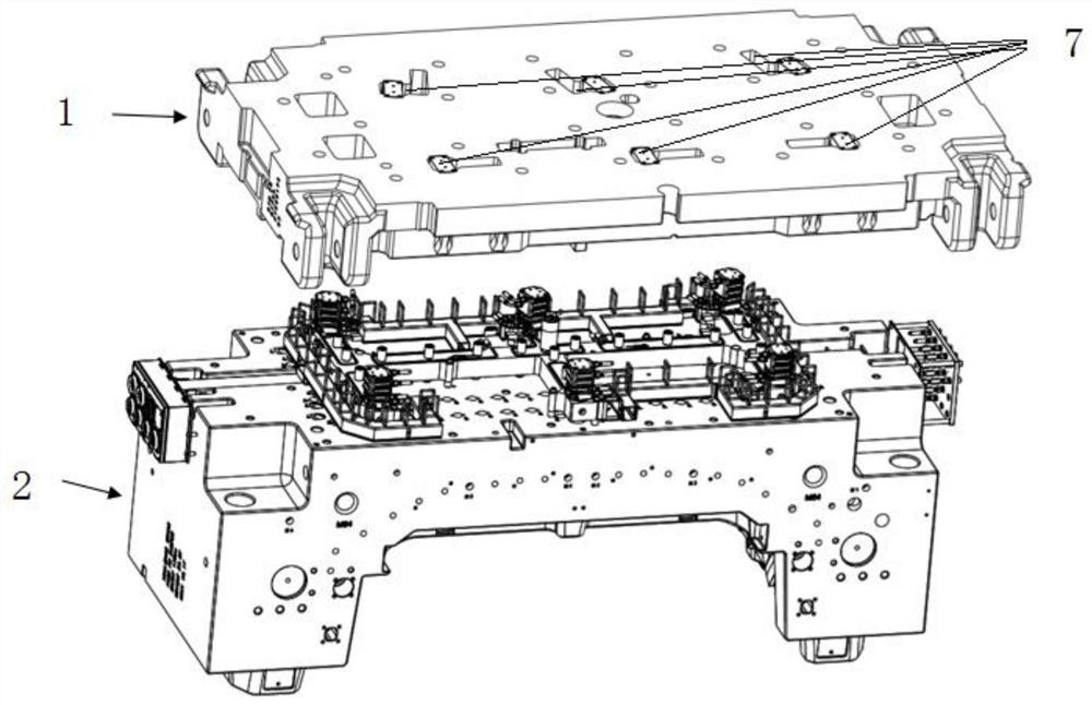
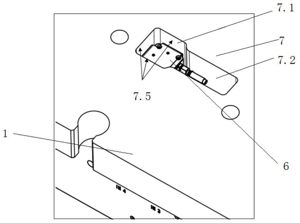
[0023] Such as Figure 1-3 As shown, the connecting plate 1 is connected to the injection molding cavity 2, and a hot runner is provided between the connecting plate 1 and the injection molding cavity 2, and the valve pin controlling the hot runner is connected to the piston rod of the oil cylinder 6 (not shown in the prior art figure) . The connecting plate 1 is made of cast iron, also known as cast iron plate. The connecting plate 1 is fixedly connected and bon...


PUM


Abstract

The invention discloses a hot runner oil cylinder cooling structure and a mounting method thereof. The hot runner oil cylinder cooling structure comprises an injection molding machine back plate and aconnecting plate which is connected with the injection molding machine back plate and used for arranging a hot runner, wherein the connecting plate is provided with an oil cylinder body hole used forcontaining a hot runner valve needle; a first cooling fin assembly is arranged between the oil cylinder body hole and the side wall of an oil cylinder body; and a second cooling fin assembly is arranged between the top face of the oil cylinder body and the injection molding machine back plate. According to the structure, the oil cylinder body hole in the connecting plate and the space between theoil cylinder body hole and the injection molding machine back plate are fully utilized, the problem of oil cylinder cooling is solved in the narrow space, and the problem of oil cylinder cooling after a water cooling system loses efficacy is solved. The structure that two cooling components are elastically attached is adopted in the second cooling fin assembly, on one hand, heat transfer is achieved, more importantly, the problem of how to arrange the cooling components in the narrow space is solved, and the situation that the oil cylinder is extruded after assembling, and consequently the machining precision of the cooling components is reduced is avoided.

Description

technical field [0001] The invention belongs to the cooling technology of an injection molding structure, and in particular relates to a cooling technology of a hot runner of an injection mold. Background technique [0002] The needle-type hot runner of the injection mold is set on the connection plate connected to the back plate of the injection molding machine, and the valve needle is driven by the oil cylinder to control the opening and closing of the hot nozzle injection. Since the oil cylinder is located above the splitter plate, the oil cylinder is easily damaged due to high temperature radiation, so the hot runner system will be designed to cool the oil cylinder. Currently, water cooling is usually used. A cooling water plate is installed between the oil cylinder and the splitter plate, but due to space constraints, the maximum diameter of the flow channel in the cooling water plate can only be designed to be φ6mm under the requirement of ensuring the strength of the...

Claims


Application Information

Patent Timeline
Patent Type & Authority Applications(China)
IPC IPC(8): B29C45/27B29C45/28
CPCB29C45/2737B29C45/281B29C2045/2753
Inventor 陈奎李十全王龙何继辉马云超贺倩郑根保陈飞甘学文
Owner DONGFENG HONDA AUTOMOBILE CO LTD
Learn More