
Novel wind power generation device and assembly and power generation method

A wind power generation device and a new type of technology, which are applied in wind turbine combinations, electromechanical devices, wind energy power generation, etc., can solve the problems of inconvenient installation and debugging, high equipment cost, and low power generation efficiency.

Pending Publication Date: 2021-02-23
袁立新
View PDF0 Cites 0 Cited by
  • Summary
  • Abstract
  • Description
  • Claims
  • Application Information

AI Technical Summary

Problems solved by technology

However, this kind of wind generator still has great deficiencies, such as high equipment cost, inconvenient installation and debugging, etc., and at least the rated wind speed must be reached before the rated power can be output. For directional control, it is not suitable for wind in all directions, and the power generation efficiency is low

Method used


Image

  • Novel wind power generation device and assembly and power generation method
  • Novel wind power generation device and assembly and power generation method
  • Novel wind power generation device and assembly and power generation method

Examples


Embodiment 1

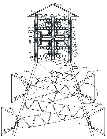
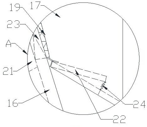
[0059] like figure 1 and Figure 5 As shown, a new type of wind power generation device includes a generator tube 9 and an induced draft tube 16 located below the generator tube, and the generator tube 9 communicates with the induced draft tube 16 . The air-inducing tube 16 has a small upper part and a lower part in a conical shape, and several air-intake tubes 17 are arranged on the outer wall of the air-inducing tube 16 . Preferably, several described air inlet tubes 17 are divided into several layers from top to bottom along the air induction tube 16, and the quantity of each layer of air inlet tubes is several, and the air inlet tubes are evenly distributed along the circumference of the air induction tube 16. Layout, and respectively set in four orientations of east, south, west and north ( figure 1 In order to show the details of the air duct more clearly, the air inlet tubes on the front and rear sides outside the air duct are omitted). In order to prevent wind from ...

Embodiment 2

[0085] The difference between this embodiment and embodiment one is:

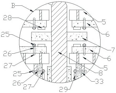
[0086] like Figure 5As shown, the first buffer mechanism includes several first rollers 31 that are annularly arranged on the axially fixed magnet 6, opposite to the first fixed magnet ring 7, and the rolling direction of each first roller 31 on the upper and lower sides is the same as that of the first roller 31. A fixed magnet ring 7 rotates in the same direction, and the first roller 31 is suspended, and neither the top nor the bottom of the first roller 31 is in contact with the axial fixed magnet 6 . The connecting column 39 of the first roller 31 passes through the fixed magnet 6 in the axial direction and is connected with a fixing anti-off piece 40 .

[0087] The second buffer mechanism includes several second rollers 32 that are annularly arranged on the radially fixed magnet 10, opposite to the second fixed magnet ring 11, and the rolling direction of the second roller 32 arranged in the circumf...


PUM


Abstract

The invention provides a novel wind power generation device and assembly and a power generation method. The wind power generation device comprises a power generation cylinder and an air inducing cylinder located below the power generation cylinder; the power generation cylinder communicates with the air inducing cylinder; a plurality of horn-shaped air inlet cylinders are arranged on the outer side wall of the air inducing cylinder; a one-way valve is arranged at the closing-in end of each air inlet cylinder; an air guiding pipe is spirally mounted on the inner side wall of the air inducing cylinder; the air inlet cylinders communicate with the air guiding pipe; a funnel-shaped air outlet with the small bottom and the large top is formed in the top end of the air guiding pipe; a rainproofcover is arranged at the top of the power generation cylinder; an air outlet is formed in the side wall of the power generation cylinder; an engine rotating shaft is arranged in the power generation cylinder; power generation fan blades are fixedly connected to the two ends of the engine rotating shaft; the engine rotating shaft and the power generation cylinder are provided with upper fixing mechanisms and rotor power generation magnets; the rotor power generation magnets are arranged below a disc fixing frame; connecting discs are connected between the rotor power generation magnets and theengine rotating shaft; and a power generation coil is arranged on the inner side wall of the power generation cylinder. The air inlet amount can be increased through the multiple air inlet cylinders,air in multiple directions can be collected, the application rate is high, and the power generation capacity is improved.

Description

technical field [0001] The invention relates to the technical field of wind power generation, in particular to a novel wind power generation device, components and power generation method. Background technique [0002] Wind power is the conversion of wind kinetic energy into electrical energy. As a clean and renewable energy source, wind energy has attracted more and more attention from all over the world. Its reserves are huge. The global wind energy is about 2.74×10^9MW, of which the usable wind energy is 2×10^7MW, which is 10 times larger than the total amount of water energy that can be developed and utilized on the earth. [0003] At present, the propeller type wind turbine is the most widely used type of wind power generation. The common ones are two-blade and three-blade wind turbines, but there are also wind turbines with one or more than four blades. The wing shape of this kind of wind turbine is similar to that of an airplane. In order to improve the starting per...

Claims


Application Information

Patent Timeline
IPC IPC(8): F03D3/04F03D9/11F03D9/25F03D80/00F03D80/30F03D1/04F03D9/32H02K7/18H02N15/00H02S10/12
CPCF03D1/04F03D3/005F03D3/04F03D9/007F03D9/11F03D9/32F03D80/00F03D80/30F03D9/255H02K7/183H02K7/1838H02N15/00H02S10/12Y02E10/50Y02E10/72Y02E10/728Y02E10/74Y02E70/30Y02A30/14
Inventor 袁立新
Owner 袁立新
Learn More