Self-adaptive structure capable of self-adapting to size of embedded hole and embedded cooker
A self-adaptive and dimensional technology, applied in the field of stoves, can solve the problems that the risk of cabinet scratches in the shaking gap cannot be completely eliminated, the installation is complicated, etc., and achieve the effect of simple structure and strong self-adaptability
- Summary
- Abstract
- Description
- Claims
- Application Information
AI Technical Summary
Problems solved by technology
Method used
Image

Examples
Embodiment 1
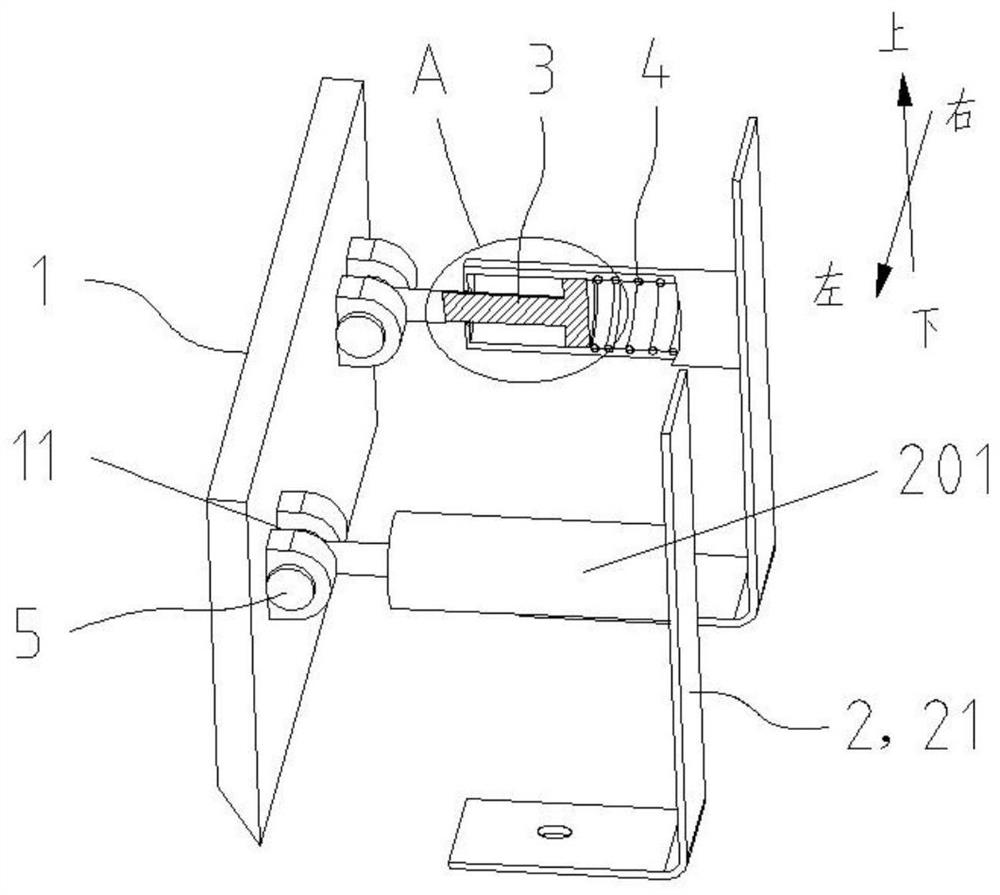
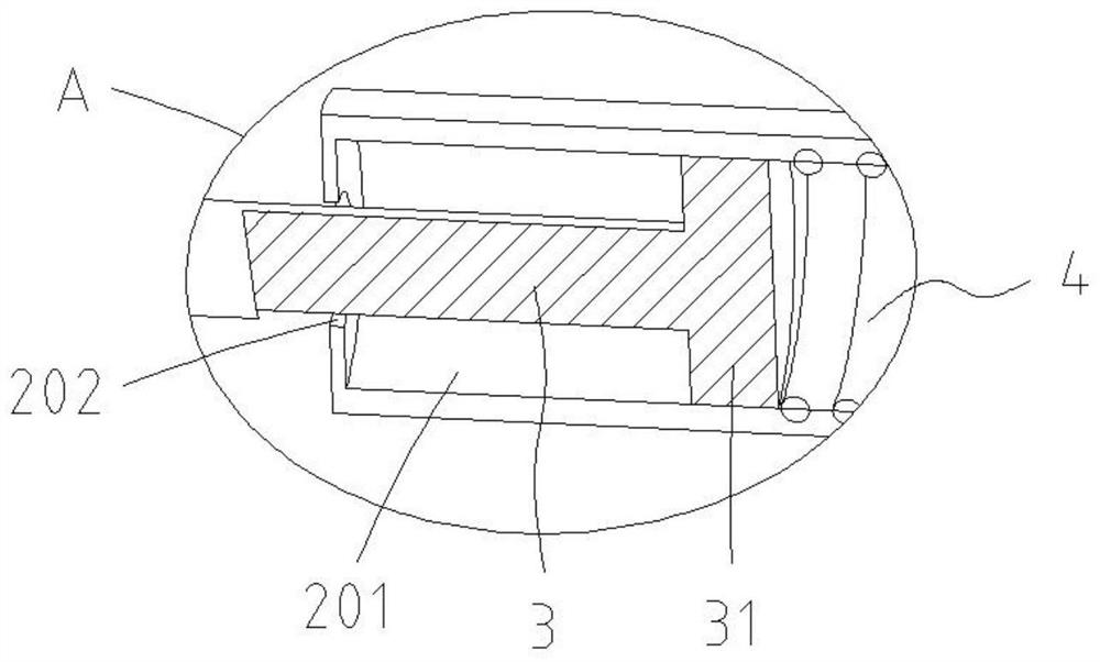
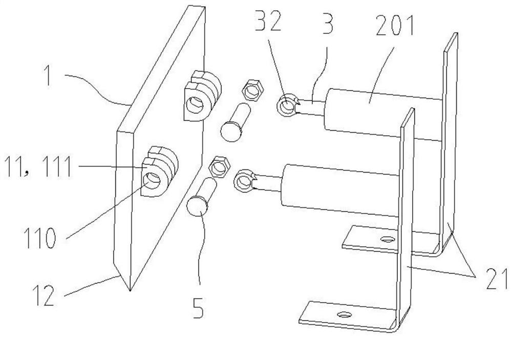
[0033] Referring to 1-4, this embodiment provides an adaptive structure that adapts to the size of the embedded hole. The adaptive structure includes a pressure-bearing member 1, a bracket 2, a pull rod 3 and an elastic member 4, wherein the pressure-bearing member 1 is used for abut against the inner wall of the mounting hole. The bracket 2 is used to connect with the bottom shell of the cooker, and the bracket 2 is provided with a mounting column extending toward the direction of the pressure-bearing part 1 and arranged laterally, and an installation cavity 201 is defined inside the mounting column, and the mounting column faces the pressure-bearing part 1 A hole 202 is provided on one side, the hole 202 faces the pressure bearing part 1 and communicates with the installation cavity 201 . One end of the pull rod 3 is telescopically and movably arranged in the installation cavity 201, and the other end passes through the opening 202 to hinge the pressure bearing 1, so that th...
Embodiment 2
[0051] see Figure 8 , The difference between this embodiment and Embodiment 1 is that the structure of the bracket 2 is different. Specifically, the bracket 2 includes a bottom surface 22 and two support surfaces 23, the lower ends of the two support surfaces 23 are respectively integrally formed with the bottom surface 22, and each support surface 23 is provided with a mounting column extending toward the direction of the pressure bearing member 1. The mounting post has a mounting cavity 201 and an opening 202 communicating with the mounting cavity 201 . Two fixing holes 203 are provided on the bottom surface 22. When the self-adaptive structure is installed on the bottom shell of the cooker, two screws can pass through the two fixing holes 203 respectively and then be detachably connected with the bottom shell of the cooker, or the bottom surface 22 It is fixedly connected with the bottom shell of the cooker by bonding or welding. In this embodiment, the connection betwee...
Embodiment 3
[0054] see Figure 9 , The difference between this embodiment and Embodiment 1 is that the structure of the bracket 2 is different. Specifically, the bracket 2 includes a bottom surface 22 and a support surface 23. The bottom surface 22 and the support surface 23 are integrally formed to form an "L" shape with each other. The two mounting posts extending in the direction of the pressure piece 1 each have a mounting cavity 201 and an opening 202 communicating with the mounting cavity 201 , and the other parts are the same as in the first embodiment.
[0055] It can be seen that by arranging two mounting columns with mounting cavities 201 and openings 202 side by side on the same support surface 23 at intervals, the overall area of the support surface 23 is larger, further enhancing the strength of the support surface 23, and avoiding the elastic deformation of the support surface 23. Deformation occurs under the action of component 4; in addition, by setting two fixing holes...
PUM
 Abstract
Description
Claims
Application Information
 - R&D
- Intellectual Property
- Life Sciences
- Materials
- Tech Scout
- Unparalleled Data Quality
- Higher Quality Content
- 60% Fewer Hallucinations
Browse by: Latest US Patents, China's latest patents, Technical Efficacy Thesaurus, Application Domain, Technology Topic, Popular Technical Reports.
© 2025 PatSnap. All rights reserved.Legal|Privacy policy|Modern Slavery Act Transparency Statement|Sitemap|About US| Contact US: help@patsnap.com